Sony DVWM2000 Product Manual (Operation Manual 1st Edition (Revised 6)) - Page 125
Item number, Settings, CONTROL PANEL, REMOTE, NOT CLEAR, WHEN FORMAT, 4F/8F, I&O, PANEL - dvw m2000p manual
 |
View all Sony DVWM2000 manuals
Add to My Manuals
Save this manual to your list of manuals |
Page 125 highlights
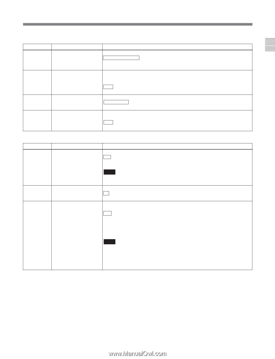
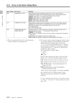
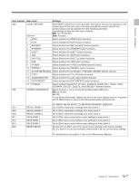
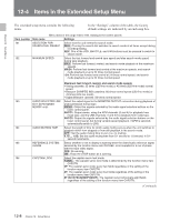
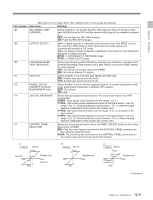
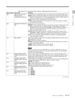
Chapter 12 Setup Menus Menu items in the range 100 to 199, relating to the control panels (Continued) Item number Item name Settings 133 TELE-FILE CONTROL Selects the device used for data modification operations in the Tele-File menu. MODE CONTROL PANEL : Operate with the control panel of this unit. REMOTE: Operate with remote devices connected to connectors such as REMOTE1, REMOTE2, and RS-232C. 134 TELE-FILE MENU AUTO Selects whether to open the Tele-File menu automatically when a cassette with a POPUP Tele-File label is loaded. However, this is valid only when the function menu is HOME, HOME2, or page 1 to 6. OFF : Do not open the Tele-File menu automatically. ON: Open the Tele-File menu automatically. 135 TELE-FILE THREAD Selects whether to clear the thread counter when formatting a Tele-File. COUNTER CLEAR MODE NOT CLEAR : Do not clear the thread counter. WHEN FORMAT: Clear the thread counter. 136 TELE-FILE IN OUT INPUT Selects whether to continuously input log (IN and OUT point) data in the Tele-File CONTINUE menu screen. OFF : Do not continuously input log (IN and OUT point) data. ON : Continuously input log (IN and OUT point) data. Menu items in the range 200 to 299, relating to the remote control interface Item number Item name Settings 201 PARA RUN Select whether or not to use synchronized operation for two or more VTRs. DIS : No synchronized operation ENA: Use synchronized operation Note To use synchronized operation for two or more VTRs, set item 201 to "ENA" on all of the VTRs. 202 CF FLAG (DVW-M2000P/ Select the mode for locking to the color framing sent from the remote controller. 2000P only) 8F : Eight-field locking mode 4F/8F: Four- or eight-field locking mode 211 REMOTE1 PORT Select how to use the REMOTE 1-IN(9P) and REMOTE 1-OUT(9P) connectors on the connector panel. I&O : Both the IN and OUT connectors are effective whether in local or remote mode. IN: Only the IN connector is effective whether in local or remote mode. OUT: Only the OUT connector is effective whether in local or remote mode. PANEL: Allows you to select i&o, in, or out using the function menu. Note When selecting "PANEL", first define user-defined function key RMT1 in the HOME2 page. On how to define user-defined function keys in the HOME2 page, refer to the Maintenance Manual Volume 1. 12-11 Chapter 12 Setup Menus
-
 1
1 -
2
-
3
-
4
-
5
-
6
-
7
-
8
-
9
-
10
-
11
-
12
-
13
-
14
-
15
-
16
-
17
-
18
-
19
-
20
-
21
-
22
-
23
-
24
-
25
-
26
-
27
-
28
-
29
-
30
-
31
-
32
-
33
-
34
-
35
-
36
-
37
-
38
-
39
-
40
-
41
-
42
-
43
-
44
-
45
-
46
-
47
-
48
-
49
-
50
-
51
-
52
-
53
-
54
-
55
-
56
-
57
-
58
-
59
-
60
-
61
-
62
-
63
-
64
-
65
-
66
-
67
-
68
-
69
-
70
-
71
-
72
-
73
-
74
-
75
-
76
-
77
-
78
-
79
-
80
-
81
-
82
-
83
-
84
-
85
-
86
-
87
-
88
-
89
-
90
-
91
-
92
-
93
-
94
-
95
-
96
-
97
-
98
-
99
-
100
-
101
-
102
-
103
-
104
-
105
-
106
-
107
-
108
-
109
-
110
-
111
-
112
-
113
-
114
-
115
-
116
-
117
-
118
-
119
-
 120
120 -
 121
121 -
 122
122 -
 123
123 -
 124
124 -
 125
125 -
 126
126 -
 127
127 -
 128
128 -
 129
129 -
 130
130 -
131
-
132
-
133
-
134
-
135
-
136
-
137
-
138
-
139
-
140
-
141
-
142
-
143
-
144
-
145
-
146
-
147
-
148
-
149
-
150
-
151
-
152
-
153
-
154
-
155
-
156
-
157
-
158
-
159
-
160
-
161
-
162
-
163
-
164
 |
 |