Sony DVWM2000 Product Manual (Operation Manual 1st Edition (Revised 6)) - Page 127
Item number, Settings, N-STD, AUTO1, CRASH, VIDEO, AUDIO, NODEF, CH1+2, SERVO/AV REFERENCE
 |
View all Sony DVWM2000 manuals
Add to My Manuals
Save this manual to your list of manuals |
Page 127 highlights
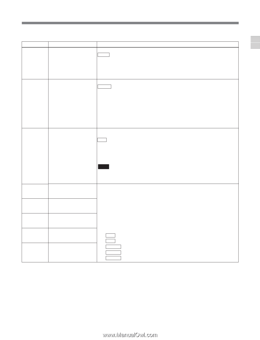
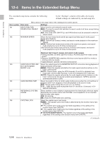
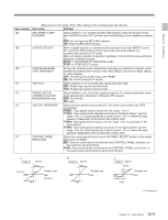
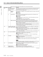
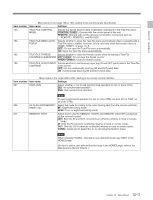
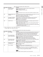
Chapter 12 Setup Menus Menu items in the range 300 to 399, relating to editing operations (Continued) Item number Item name Settings 308 SELECTION OF STD/ Select the STD or NON-STD mode in accordance with a composite video input. NON-STD FOR AUTO : Detect automatically whether the input video luminance and chrominance COMPOSITE VIDEO IN signals are interleaved or not. If they are interleaved, select the STD mode. If they are not interleaved, select the NON-STD mode. STD: The STD mode is always used (forced STD mode). N-STD: Use this setting when color framing of the input video signal is unstable (forced NON-STD mode). 309 SERVO/AV REFERENCE Select the servo reference signal. SEL AUTO1 : During recording, an analog component/composite or digital input video signal is used as the servo reference signal. During playback, the signal selected by the function menu item OUTREF is used as the servo reference signal. If the signal selected by the OUTREF setting is not connected, an internal reference signal is used. AUTO2: When the function menu item OUTREF is set to REF, and any of the ASSEMBLE, VIDEO, AUDIO CH1 to CH8 and TC buttons is lit, the reference signal for video/audio signal processing is locked to the input video signal. EXT: The servo reference signal is forced to be "EXT" (an external reference video input signal is used). 310 REC INHIBIT Select the conditions under which recording is inhibited when the function menu item RECINH is set to ON. ALL : All tape recording is inhibited. CRASH: Normal tape recording is inhibited. Select this setting when you wish to carry out assemble editing. VIDEO: Inhibit recording of video and CTL signals. AUDIO: Inhibit recording of audio and CTL signals. Note When the function menu item RECINH is set to ON, the REC INHI indicator on the lower control panel lights. If an operation inhibited by this item is attempted, the REC INHI indicator flashes. 311 ANALOG AUDIO EDIT When using an editor (PVE-500, BVE-600, etc.) or a remote controller which PRESET REPLACE FOR cannot control digital audio edit preset, select how to activate edit preset of each CH1 digital audio channel (channels 1 to 4) on this unit using the analog audio edit 312 ANALOG AUDIO EDIT PRESET REPLACE FOR CH2 preset function of the editor or remote controller. Set edit preset of each digital audio channel of this unit on or off according to the analog audio preset specified by the remote controller or editor. NODEF: No definition. 313 ANALOG AUDIO EDIT CH1: Follow edit preset of analog channel 1. PRESET REPLACE FOR CH2: Follow edit preset of analog channel 2. CH3 CH1+2: Follow edit preset of analog channel 1 or 2. 314 ANALOG AUDIO EDIT The default settings for each item are as follows: PRESET REPLACE FOR 311: CH1 CH4 312: CH2 315 ANALOG AUDIO EDIT 313: NODEF RESET REPLACE FOR CUE 314: NODEF 315: NODEF (Continued) 12-13 Chapter 12 Setup Menus
-
 1
1 -
2
-
3
-
4
-
5
-
6
-
7
-
8
-
9
-
10
-
11
-
12
-
13
-
14
-
15
-
16
-
17
-
18
-
19
-
20
-
21
-
22
-
23
-
24
-
25
-
26
-
27
-
28
-
29
-
30
-
31
-
32
-
33
-
34
-
35
-
36
-
37
-
38
-
39
-
40
-
41
-
42
-
43
-
44
-
45
-
46
-
47
-
48
-
49
-
50
-
51
-
52
-
53
-
54
-
55
-
56
-
57
-
58
-
59
-
60
-
61
-
62
-
63
-
64
-
65
-
66
-
67
-
68
-
69
-
70
-
71
-
72
-
73
-
74
-
75
-
76
-
77
-
78
-
79
-
80
-
81
-
82
-
83
-
84
-
85
-
86
-
87
-
88
-
89
-
90
-
91
-
92
-
93
-
94
-
95
-
96
-
97
-
98
-
99
-
100
-
101
-
102
-
103
-
104
-
105
-
106
-
107
-
108
-
109
-
110
-
111
-
112
-
113
-
114
-
115
-
116
-
117
-
118
-
119
-
120
-
121
-
 122
122 -
 123
123 -
 124
124 -
 125
125 -
 126
126 -
 127
127 -
 128
128 -
 129
129 -
 130
130 -
 131
131 -
 132
132 -
133
-
134
-
135
-
136
-
137
-
138
-
139
-
140
-
141
-
142
-
143
-
144
-
145
-
146
-
147
-
148
-
149
-
150
-
151
-
152
-
153
-
154
-
155
-
156
-
157
-
158
-
159
-
160
-
161
-
162
-
163
-
164
 |
 |