Sony DVWM2000 Product Manual (Operation Manual 1st Edition (Revised 6)) - Page 120
TTL: 00: 00, Item number, Settings, WHITE, BLACK, W/OUT, disable
 |
View all Sony DVWM2000 manuals
Add to My Manuals
Save this manual to your list of manuals |
Page 120 highlights
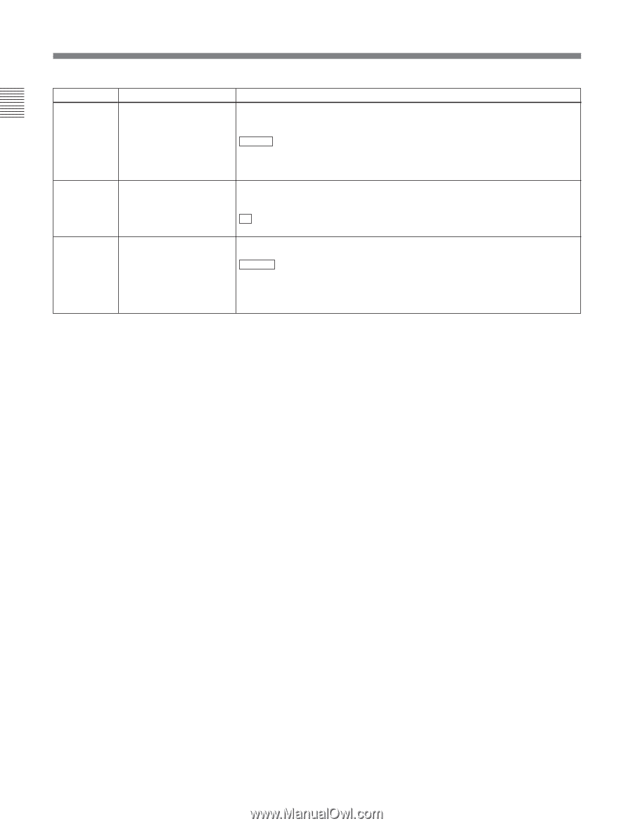
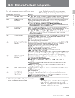
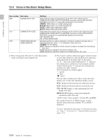
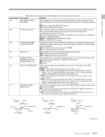
Chapter 12 Setup Menus 12-3 Items in the Basic Setup Menu Item number Item name 009a) CHARACTER TYPE 011a) CHARACTER V-SIZE 012b) CONDITION DISPLAY VIDEO MONTOR Settings Determines the type of characters such as time code output from the COMPOSITE VIDEO OUTPUT 3(SUPER) connector and the SDI OUTPUT 3(SUPER) connector for superimposed display on the monitor. WHITE : White letters on a black background BLACK: Black letters on a white background W/OUT: White letters with black outline B/OUT: Black letters with white outline Determines the vertical size of characters such as time code output from the COMPOSITE VIDEO OUTPUT 3(SUPER) connector and the SDI OUTPUT 3(SUPER) connector for superimposed display on the monitor. ×1 : Standard size ×2: 2 times standard size Specifies whether to add an indication of channel condition and tape time to superimposed text, when "×1" is selected in menu item 011. disable : Do not display ena1: Display an indication of both channel condition and tape time (remaining time, etc.) ena2: Display an indication of channel condition only ena3: Display an indication of tape time (remaining time, etc.) only a) When setting items 009 and 011, watch the monitor screen, and adjust to the required state. b) The channel condition indication appears under the timer or status line (under the video playback level indication during playback of an analog tape), in the format "V-A-", where the symbol following the "V" indicates the rotating head condition for video channels and the symbol following the "A" indicates the rotating head condition for audio channels. The following three symbols appear: "-" (good) "*" (fair) "x" (poor) The tape time is displayed as follows in the time data display area 2 of the time data/menu display section. BOT: Displayed when the tape has returned to the top. EOT: Displayed when the tape has reached the end. TTL: 00: 00: Displays a time representing the total length of the tape. REM: 00: 00: Displays a time representing the remaining length of the tape. "00:00" means "hours:minutes" for both TTL and REM. The setting of item F5 (T INFO) on page 3 of the function menu determines whether TTL or REM is displayed. For more information about page 3 of the function menu, see "Page 3" in Section 11-2 "Function Menu Item List" (page 11-6). 12-6 Chapter 12 Setup Menus
-
 1
1 -
2
-
3
-
4
-
5
-
6
-
7
-
8
-
9
-
10
-
11
-
12
-
13
-
14
-
15
-
16
-
17
-
18
-
19
-
20
-
21
-
22
-
23
-
24
-
25
-
26
-
27
-
28
-
29
-
30
-
31
-
32
-
33
-
34
-
35
-
36
-
37
-
38
-
39
-
40
-
41
-
42
-
43
-
44
-
45
-
46
-
47
-
48
-
49
-
50
-
51
-
52
-
53
-
54
-
55
-
56
-
57
-
58
-
59
-
60
-
61
-
62
-
63
-
64
-
65
-
66
-
67
-
68
-
69
-
70
-
71
-
72
-
73
-
74
-
75
-
76
-
77
-
78
-
79
-
80
-
81
-
82
-
83
-
84
-
85
-
86
-
87
-
88
-
89
-
90
-
91
-
92
-
93
-
94
-
95
-
96
-
97
-
98
-
99
-
100
-
101
-
102
-
103
-
104
-
105
-
106
-
107
-
108
-
109
-
110
-
111
-
112
-
113
-
114
-
 115
115 -
 116
116 -
 117
117 -
 118
118 -
 119
119 -
 120
120 -
 121
121 -
 122
122 -
 123
123 -
 124
124 -
 125
125 -
126
-
127
-
128
-
129
-
130
-
131
-
132
-
133
-
134
-
135
-
136
-
137
-
138
-
139
-
140
-
141
-
142
-
143
-
144
-
145
-
146
-
147
-
148
-
149
-
150
-
151
-
152
-
153
-
154
-
155
-
156
-
157
-
158
-
159
-
160
-
161
-
162
-
163
-
164
 |
 |