Sony DVWM2000 Product Manual (Operation Manual 1st Edition (Revised 6)) - Page 25
Editing mode setting ALARM indicator and KEY INHI, indicator, VIDEO button
 |
View all Sony DVWM2000 manuals
Add to My Manuals
Save this manual to your list of manuals |
Page 25 highlights
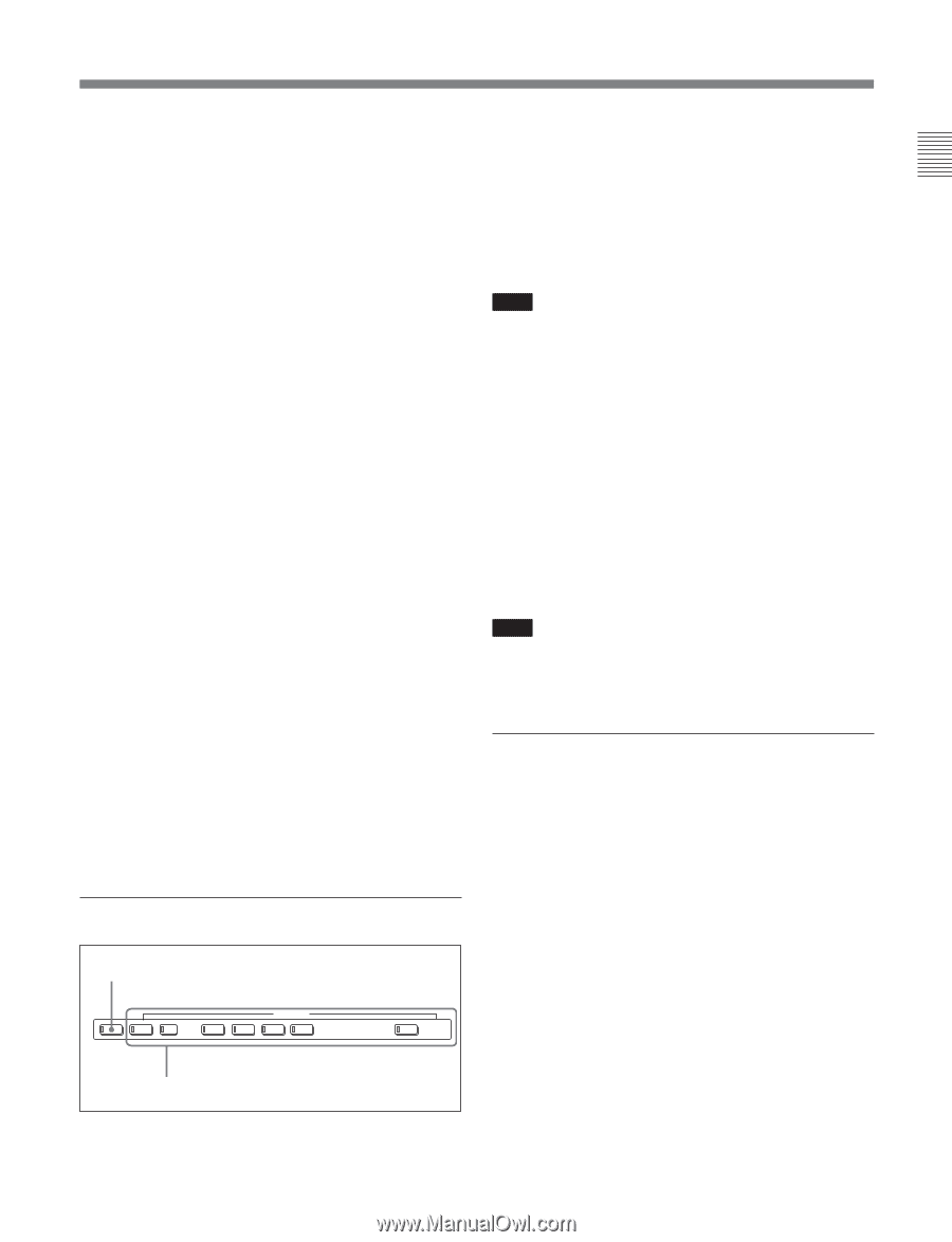
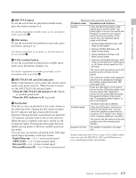
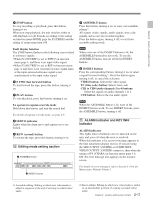
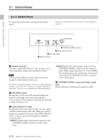
Chapter 2 Location and Function of Parts 5 STOP button To stop recording or playback, press this button, turning it on. When you stop playback, the unit switches either to still playback or to E-E mode according to the setting on function menu HOME page for F2 (PB/EE) and the setting of setup menu item 108. Fault display function The STOP button flashes in the following cases related to reference signals: • When F2 (OUTREF) is set to INPUT on function menu page 4, and there is no input video signal. • When F2 (OUTREF) is set to REF in function menu page 4, and there is no external reference signal input or the input external reference signal is not synchronized to the input video signal. 6 F FWD (fast forward) button To fast forward the tape, press this button, turning it on. 7 PLAY button To start playback, press this button, turning it on. To operate in capstan override mode Hold down this button, and turn the search dial. For details of capstan override mode, see page 4-9. 8 SERVO indicator Lights when the drum servo and capstan servo are locked. 9 REW (rewind) button To rewind the tape, press this button, turning it on. q; Editing mode setting section 1 ASSEMBLE button ASSEMBLE INSERT VIDEO TC CH1 CH2 CH3 CH4 CUE 2 INSERT buttons 1 ASSEMBLE button Press this button, turning it on, to carry out assemble editing 1). All signals (video signals, audio signals, time code signals, and so on) are recorded together. Press the button again, turning it off, to exit from assemble editing mode. Note When even one of the INSERT buttons is lit, the ASSEMBLE button does not work. To use the ASSEMBLE button, turn off all the lit INSERT buttons. 2 INSERT buttons Press the corresponding button, turning it on, to select a signal for insert editing 2). Press the button again, turning it off, to cancel the selection. VIDEO button: Selects the video signal. TC (time code) button: Selects time code. CH1 to CH4 (audio channels 1 to 4) buttons: Select the signals on audio channels 1 to 4. CUE button: Selects the cue audio signal. Note When the ASSEMBLE button is lit, none of the INSERT buttons work. To use INSERT buttons, press the ASSEMBLE button, turning it off. qa ALARM indicator and KEY INHI indicator ALARM indicator This lights when a hardware error is detected on the unit, and goes off when the error is resolved. When this indicator is lit, an error message appears in the time data/menu display section. If you are using the SDI OUTPUT 3(SUPER) or COMPOSITE VIDEO OUTPUT 3(SUPER) connector, then when the setting of F4 (CHARA) in function menu page 4 is ON, the error message also appears on the monitor screen. For details on error messages, refer to Section 1-24 in the Maintenance Manual Volume 1. ... 1) Assemble editing: Editing in which new video/audio is added in sequence to the end of existing recorded video/ audio. 2) Insert editing: Editing in which new video/audio is added to an intermediate position of existing recorded video/ audio. 2-11 Chapter 2 Location and Function of Parts
-
 1
1 -
2
-
3
-
4
-
5
-
6
-
7
-
8
-
9
-
10
-
11
-
12
-
13
-
14
-
15
-
16
-
17
-
18
-
19
-
 20
20 -
 21
21 -
 22
22 -
 23
23 -
 24
24 -
 25
25 -
 26
26 -
 27
27 -
 28
28 -
 29
29 -
 30
30 -
31
-
32
-
33
-
34
-
35
-
36
-
37
-
38
-
39
-
40
-
41
-
42
-
43
-
44
-
45
-
46
-
47
-
48
-
49
-
50
-
51
-
52
-
53
-
54
-
55
-
56
-
57
-
58
-
59
-
60
-
61
-
62
-
63
-
64
-
65
-
66
-
67
-
68
-
69
-
70
-
71
-
72
-
73
-
74
-
75
-
76
-
77
-
78
-
79
-
80
-
81
-
82
-
83
-
84
-
85
-
86
-
87
-
88
-
89
-
90
-
91
-
92
-
93
-
94
-
95
-
96
-
97
-
98
-
99
-
100
-
101
-
102
-
103
-
104
-
105
-
106
-
107
-
108
-
109
-
110
-
111
-
112
-
113
-
114
-
115
-
116
-
117
-
118
-
119
-
120
-
121
-
122
-
123
-
124
-
125
-
126
-
127
-
128
-
129
-
130
-
131
-
132
-
133
-
134
-
135
-
136
-
137
-
138
-
139
-
140
-
141
-
142
-
143
-
144
-
145
-
146
-
147
-
148
-
149
-
150
-
151
-
152
-
153
-
154
-
155
-
156
-
157
-
158
-
159
-
160
-
161
-
162
-
163
-
164
 |
 |