Yamaha MOTIF7 Owner's Manual - Page 169
F4] Common, Contr, oller Assign, Effect, Connection, Control Change Numbers, VCE INS Voice, Insertion
 |
View all Yamaha MOTIF7 manuals
Add to My Manuals
Save this manual to your list of manuals |
Page 169 highlights
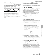
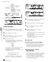
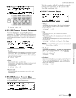
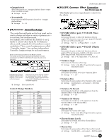
• OutputSwitch When this is set to on, Arpeggio playback data is output from the MIDI terminal. ❏ Settings on, off • TransmitCh Determines the MIDI transmit channel for Arpeggio playback data. ❏ Settings 1 ~ 16 ● [F4] Common Controller Assign The controllers and knobs on the front panel can be used to change and adjust a variety of parameters - in real time, and simultaneously. For example, you could use the ASSIGN 1 and 2 knobs to control effect depth for two different effects, while using the Foot Controller to control modulation. These control assignments are called "Controller Assign." You can have independent Controller Assign settings for each performance. Set the Control Change number for the Breath Controller. The function set here can be controlled by the Breath Controller connected to the BREATH CONTROLLER (page 28) jacks on the rear panel. Determines the Control Change numbers for the ASSIGN 1 and 2 knobs on the front panel. Determines the Control Change numbers for Foot Controllers 1 and 2. To control these functions, connect Foot Controllers to the FOOT CONTROLLER jacks on the rear panel (page 28). ❏ Settings (See chart below) Control Change Numbers LCD 00 off 32 01 ModWheel 64 02 Breath 65 04 FootCtrl 66 05 PortTime 67 06 Data Ent 72 07 MainVol 74 10 Panpot 75 11 Express 84 16 General 1 91 17 General 2 92 18 General 3 93 19 General 4 LCD off Sustain PortaSw Sostenut Soft Release Bright Decay PortaCtl Effect 1 Effect 2 Effect 3 Performance Edit mode ● [F6]-[SF1] Common Effect Connection Basic Structure (page 40) This display gives you comprehensive control over the effects. • EF PART (Effect part) ➡ VCE INS (Voice Insertion) Determines the part to which the Insertion effect is applied. The Insertion connection type (page 40) depends on the voice of the selected part. ❏ Settings Part 1 ~ 4, Plug-in Part 1 ~ 3, off • EF PART (Effect part) ➡ PLG-EF (Plug-in Efect) Determines the part to which the Insertion effect is applied. This parameter is available only when a special Effect Plug-in board (VH) has been installed. ❏ Settings Part 1~4, Plug-in Part 1~3, A/D, off • Variation Type Determines the Variation effect type. ❏ Settings Refer to the Effect Types list in the separate Data List booklet. • Variation Return Determines the Return level of the Variation Effect. ❏ Settings 0 ~ 127 • Variation Pan Determines the pan position of the Variation effect sound. ❏ Settings L64 (far left) ~cnt (center) ~ R63 (far right) • Variation To Reverb Determines the Send level of the signal sent from the Variation Effect to the Reverb Effect. ❏ Settings 0 ~ 127 • Variation To Chorus Determines the Send level of the signal sent from the Variation Effect to the Chorus Effect. ❏ Settings 0 ~ 127 • Chorus Type Determines the Chorus effect type. ❏ Settings Refer to the Effect Types list in the separate Data List booklet. • Chorus Return Level) Determines the Return level of the Chorus Effect. ❏ Settings 0 ~ 127 • Chorus Pan Determines the pan position of the Chorus effect sound. ❏ Settings L64 (far left) ~ cnt (center) ~ R63 (far right) MOTIF Reference 169 Reference Performance mode
-
 1
1 -
2
-
3
-
4
-
5
-
6
-
7
-
8
-
9
-
10
-
11
-
12
-
13
-
14
-
15
-
16
-
17
-
18
-
19
-
20
-
21
-
22
-
23
-
24
-
25
-
26
-
27
-
28
-
29
-
30
-
31
-
32
-
33
-
34
-
35
-
36
-
37
-
38
-
39
-
40
-
41
-
42
-
43
-
44
-
45
-
46
-
47
-
48
-
49
-
50
-
51
-
52
-
53
-
54
-
55
-
56
-
57
-
58
-
59
-
60
-
61
-
62
-
63
-
64
-
65
-
66
-
67
-
68
-
69
-
70
-
71
-
72
-
73
-
74
-
75
-
76
-
77
-
78
-
79
-
80
-
81
-
82
-
83
-
84
-
85
-
86
-
87
-
88
-
89
-
90
-
91
-
92
-
93
-
94
-
95
-
96
-
97
-
98
-
99
-
100
-
101
-
102
-
103
-
104
-
105
-
106
-
107
-
108
-
109
-
110
-
111
-
112
-
113
-
114
-
115
-
116
-
117
-
118
-
119
-
120
-
121
-
122
-
123
-
124
-
125
-
126
-
127
-
128
-
129
-
130
-
131
-
132
-
133
-
134
-
135
-
136
-
137
-
138
-
139
-
140
-
141
-
142
-
143
-
144
-
145
-
146
-
147
-
148
-
149
-
150
-
151
-
152
-
153
-
154
-
155
-
156
-
157
-
158
-
159
-
160
-
161
-
162
-
163
-
 164
164 -
 165
165 -
 166
166 -
 167
167 -
 168
168 -
 169
169 -
 170
170 -
 171
171 -
 172
172 -
 173
173 -
 174
174 -
175
-
176
-
177
-
178
-
179
-
180
-
181
-
182
-
183
-
184
-
185
-
186
-
187
-
188
-
189
-
190
-
191
-
192
-
193
-
194
-
195
-
196
-
197
-
198
-
199
-
200
-
201
-
202
-
203
-
204
-
205
-
206
-
207
-
208
-
209
-
210
-
211
-
212
-
213
-
214
-
215
-
216
-
217
-
218
-
219
-
220
-
221
-
222
-
223
-
224
-
225
-
226
-
227
-
228
-
229
-
230
-
231
-
232
-
233
-
234
-
235
-
236
-
237
-
238
-
239
-
240
-
241
-
242
-
243
-
244
-
245
-
246
-
247
-
248
-
249
-
250
-
251
-
252
-
253
-
254
-
255
-
256
-
257
-
258
-
259
-
260
-
261
-
262
-
263
-
264
-
265
-
266
-
267
-
268
-
269
-
270
-
271
-
272
-
273
-
274
-
275
-
276
-
277
-
278
-
279
-
280
-
281
-
282
-
283
-
284
-
285
-
286
-
287
-
288
-
289
-
290
-
291
-
292
-
293
-
294
-
295
-
296
-
297
-
298
-
299
-
300
 |
 |
