Alpine IVA D106 Owner's Manual - Page 87
RGB Cable Included with NVE-N852A/NVE-N872A, Audio Input Connector AUX/CAMERA IN Yellow - aux input
 |
UPC - 793276200594
View all Alpine IVA D106 manuals
Add to My Manuals
Save this manual to your list of manuals |
Page 87 highlights
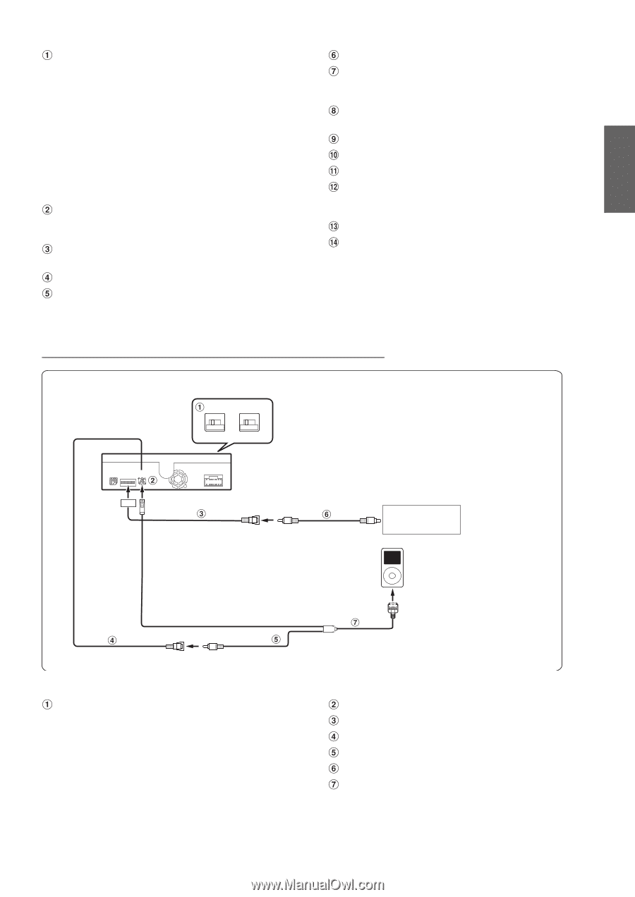
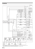
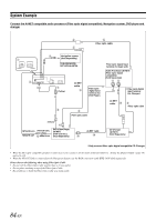
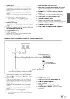
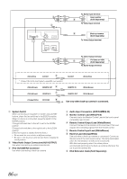
System Switch When connecting an equalizer or divider using Ai-NET feature, place the two switches in the EQ/DIV position. When no device is connected, leave the switch in the NORM position. Change both switches to the left to set to the NORM position. Change both switches to the right to set to the EQ/DIV position. (If the front panel is viewed from the front.) • Do not make the two switches to different settings. • Be sure to turn the power off to the unit before changing the switch position. RGB Input Terminal Connect this to the RGB output terminal of the Navigation System. RGB Cable (Included with NVE-N852A/NVE-N872A, not included with NVE-N871A) Digital Output Terminal Ai-NET Connector Connect this to the output or input connector of other product equipped with Ai-NET. Fiber optic Cable (Sold Separately) Audio Input Connector (AUX/CAMERA IN) (Yellow) Connect the video output lead of a DVD video player or DVD changer to this terminal. RCA Extension Cable (Included with DVD video player) Ai-NET Cable (Included with DVD video player) Ai-NET Cable (Included with CD Changer) To Ai-NET Connector (Gray) Remote Control Output Lead (White/Brown) Connect this lead to the remote control input lead. This lead outputs the controlling signals from the remote control. To Ai-NET Connector (Black) Ai-NET Cable (Included with Audio Processor) Connecting Video compatible iPod and Back-up Camera at the same time NORM EQ/DIV *1 (Yellow) To Video Output terminal Back-up camera (Sold Separately) Video compatible iPod (Sold Separately) *2 *1 Set "Setting the AUX Mode" (page 39) to "CAMERA." *2 Set "Setting for iPod Connection" (page 38) to "VIDEO." System Switch When connecting an equalizer or divider using Ai-NET feature, place the two switches in the EQ/DIV position. When no device is connected, leave the switch in the NORM position. Change both switches to the left to set to the NORM position. Change both switches to the right to set to the EQ/DIV position. (If the front panel is viewed from the front.) • Do not make the two switches to different settings. • Be sure to turn the power off to the unit before changing the switch position. iPod Direct Connector Audio Input Connector (AUX/CAMERA IN) iPod (V)/CAMERA Connector Video Connector RCA Extension Cable (Sold Separately) iPod Video FULL SPEED™ Connection Cable (Included) 85-EN
-
 1
1 -
2
-
3
-
4
-
5
-
6
-
7
-
8
-
9
-
10
-
11
-
12
-
13
-
14
-
15
-
16
-
17
-
18
-
19
-
20
-
21
-
22
-
23
-
24
-
25
-
26
-
27
-
28
-
29
-
30
-
31
-
32
-
33
-
34
-
35
-
36
-
37
-
38
-
39
-
40
-
41
-
42
-
43
-
44
-
45
-
46
-
47
-
48
-
49
-
50
-
51
-
52
-
53
-
54
-
55
-
56
-
57
-
58
-
59
-
60
-
61
-
62
-
63
-
64
-
65
-
66
-
67
-
68
-
69
-
70
-
71
-
72
-
73
-
74
-
75
-
76
-
77
-
78
-
79
-
80
-
81
-
 82
82 -
 83
83 -
 84
84 -
 85
85 -
 86
86 -
 87
87 -
 88
88 -
 89
89 -
 90
90 -
 91
91 -
 92
92 -
93
-
94
-
95
-
96
-
97
-
98
-
99
-
100
-
101
-
102
-
103
-
104
-
105
-
106
-
107
-
108
-
109
-
110
-
111
-
112
-
113
-
114
-
115
-
116
-
117
-
118
-
119
-
120
-
121
-
122
-
123
-
124
-
125
-
126
-
127
-
128
-
129
-
130
-
131
-
132
-
133
-
134
-
135
-
136
-
137
-
138
-
139
-
140
-
141
-
142
-
143
-
144
-
145
-
146
-
147
-
148
-
149
-
150
-
151
-
152
-
153
-
154
-
155
-
156
-
157
-
158
-
159
-
160
-
161
-
162
-
163
-
164
-
165
-
166
-
167
-
168
-
169
-
170
-
171
-
172
-
173
-
174
-
175
-
176
-
177
-
178
-
179
-
180
-
181
-
182
-
183
-
184
-
185
-
186
-
187
-
188
-
189
-
190
-
191
-
192
-
193
-
194
-
195
-
196
-
197
-
198
-
199
-
200
-
201
-
202
-
203
-
204
-
205
-
206
-
207
-
208
-
209
-
210
-
211
-
212
-
213
-
214
-
215
-
216
-
217
-
218
-
219
-
220
-
221
-
222
-
223
-
224
-
225
-
226
-
227
-
228
-
229
-
230
-
231
-
232
-
233
-
234
-
235
-
236
-
237
-
238
-
239
-
240
-
241
-
242
-
243
-
244
-
245
-
246
-
247
-
248
-
249
-
250
-
251
-
252
-
253
-
254
-
255
-
256
-
257
-
258
-
259
-
260
-
261
-
262
-
263
-
264
-
265
-
266
 |
 |