Cisco ASR1006 Hardware Installation Guide
Cisco ASR1006 - ASR 1006 Modular Expansion Base Manual
 |
UPC - 882658196423
View all Cisco ASR1006 manuals
Add to My Manuals
Save this manual to your list of manuals |
Cisco ASR1006 manual content summary:
- Cisco ASR1006 | Hardware Installation Guide - Page 1
Cisco ASR 1000 Series Aggregation Services Routers SIP and SPA Hardware Installation Guide March 29, 2012 Americas Headquarters Cisco Systems, Inc. 170 West Tasman Drive San Jose, CA 95134-1706 USA http://www.cisco.com Tel: 408 526-4000 800 553-NETS (6387) Fax: 408 527-0883 Text Part Number: OL- - Cisco ASR1006 | Hardware Installation Guide - Page 2
are shown for illustrative purposes only. Any use of actual IP addresses or phone numbers in illustrative content is unintentional and coincidental. Cisco ASR 1000 Series Aggregation Services Routers SIP and SPA Hardware Installation Guide © 2008-2012 Cisco Systems, Inc. All rights reserved. - Cisco ASR1006 | Hardware Installation Guide - Page 3
Physical Specifications 2-8 Cisco ASR1000-SIP40 Overview 2-9 Cisco ASR1000-SIP40 LEDs 2-10 Cisco ASR1000-SIP40 Physical Specifications 2-11 Cisco ASR 1013 Router and Slot Numbering for SIP 2-11 OL-14126-12 Cisco ASR 1000 Series Aggregation Services Routers SIP and SPA Hardware Installation Guide - Cisco ASR1006 | Hardware Installation Guide - Page 4
3-23 8-Port Gigabit Ethernet SPA Connectors 3-23 SFP Module Connections 3-23 10-Port Gigabit Ethernet SPA Overview 3-24 10-Port Gigabit Ethernet SPA LEDs 3-24 10-Port Gigabit Ethernet SPA Connectors 3-25 Cisco ASR 1000 Series Aggregation Services Routers SIP and SPA Hardware Installation Guide iv - Cisco ASR1006 | Hardware Installation Guide - Page 5
4-Port, and 8-Port OC-12c/STM-4 POS SPA Overview 3-48 2-Port, 4-Port, and 8-Port OC-12c/STM-4 Multirate POS SPA LEDs 3-48 2-Port, 4-Port, and 8-Port OC-12c/STM-4 Multirate POS SPA Interface Specifications 3-49 Cisco ASR 1000 Series Aggregation Services Routers SIP and SPA Hardware Installation Guide - Cisco ASR1006 | Hardware Installation Guide - Page 6
Node for ASR 1000 Series Overview 3-71 Cisco WebEx Node SPA LEDs 3-71 Cisco DSP SPA for ASR 1000 Series Overview 3-72 Understanding the Need for SPA-DSP 3-72 SPA-DSP Overview 3-72 Features of SPA-DSP 3-74 Cisco ASR 1000 Series Aggregation Services Routers SIP and SPA Hardware Installation Guide vi - Cisco ASR1006 | Hardware Installation Guide - Page 7
of a SIP 5-2 Deactivating a SIP 5-3 Reactivating a SIP 5-3 Verifying the Deactivation and Activation of a SIP 5-4 Preparing for Online Removal of a SPA 5-5 Deactivating a SPA 5-5 Reactivating a SPA 5-7 Cisco ASR 1000 Series Aggregation Services Routers SIP and SPA Hardware Installation Guide vii - Cisco ASR1006 | Hardware Installation Guide - Page 8
Node SPA 7-11 Prerequisites 7-11 Troubleshooting the 1-Port 10-Gigabit Ethernet LAN/WAN-PHY SPA for ASR 1000 Series Hardware 7-14 Feature Change to CPU-Usage show Command 7-15 Using debug Commands 7-17 Cisco ASR 1000 Series Aggregation Services Routers SIP and SPA Hardware Installation Guide viii - Cisco ASR1006 | Hardware Installation Guide - Page 9
INDEX Packing a SPA for Shipment 7-17 Packing a SIP for Shipment 7-20 Contents OL-14126-12 Cisco ASR 1000 Series Aggregation Services Routers SIP and SPA Hardware Installation Guide ix - Cisco ASR1006 | Hardware Installation Guide - Page 10
Contents Cisco ASR 1000 Series Aggregation Services Routers SIP and SPA Hardware Installation Guide x OL-14126-12 - Cisco ASR1006 | Hardware Installation Guide - Page 11
the Cisco ASR 1000 Series Aggregation Services Routers. This document also describes how to install the supported SIPs and SPAs and how to troubleshoot the installation. Document Revision History The Document Revision History records technical changes to this document. The table shows the Cisco IOS - Cisco ASR1006 | Hardware Installation Guide - Page 12
ESP-40 on Cisco ASR 1004 Router. Added information about: • Cisco ASR1000-SIP40 in Cisco IOS XE Release 3.1S (the new hardware SIP) • default maximum bandwidth of SIP-10 when SIP-40 is downgraded to SIP-10 Cisco ASR 1000 Series Aggregation Services Routers SIP and SPA Hardware Installation Guide - Cisco ASR1006 | Hardware Installation Guide - Page 13
1000BASE-BX10 SFP module for single-strand SMF, 1490-nm TX/1310-nm RX wavelength (GLC-BX-D) • Cisco 1000BASE-BX10 SFP module for single-strand SMF, 1310-nm TX/1490-nm RX wavelength (GLC-BX-U) OL-14126-12 Cisco ASR 1000 Series Aggregation Services Routers SIP and SPA Hardware Installation Guide xi - Cisco ASR1006 | Hardware Installation Guide - Page 14
and a SIP overview. For each supported SPA, provides a summary of SPA characteristics and a SPA overview. Describes the required tools, equipment, and safety guidelines for installing SIPs and SPAs. Cisco ASR 1000 Series Aggregation Services Routers SIP and SPA Hardware Installation Guide xii OL - Cisco ASR1006 | Hardware Installation Guide - Page 15
: • Cisco ASR 1000 Series Aggregation Services Routers SIP and SPA Software Configuration Guide • Cisco IOS XE software: - For Cisco IOS XE configuration information and support, refer to the Cisco IOS XE configuration guide or command reference. You can also refer to the specific Cisco IOS XE - Cisco ASR1006 | Hardware Installation Guide - Page 16
Syndication (RSS) feed and set content to be delivered directly to your desktop using a reader application. The RSS feeds are a free service and Cisco currently supports RSS version 2.0. Cisco ASR 1000 Series Aggregation Services Routers SIP and SPA Hardware Installation Guide xiv OL-14126-12 - Cisco ASR1006 | Hardware Installation Guide - Page 17
the specific SIPs and SPAs that are supported on the Cisco ASR 1000 Series Aggregation Services Routers, refer to the companion publication, Cisco ASR 1000 Series Aggregation Services Routers SIP and SPA Software Configuration Guide. Introduction to SIPs and SPAs Cisco ASR 1000 Series Aggregation - Cisco ASR1006 | Hardware Installation Guide - Page 18
• Each SPA provides a certain number of connectors, or ports, that are the interfaces to one or more networks. These interfaces can be individually configured using the Cisco IOS command-line interface (CLI). Cisco ASR 1000 Series Aggregation Services Routers SIP and SPA Hardware Installation Guide - Cisco ASR1006 | Hardware Installation Guide - Page 19
2-Port Gigabit Synchronous Ethernet SPA SPA-2X1GE-SYNC E SIP Supported: Cisco ASR1000-SIP10 Yes Yes Yes Yes Yes Yes Yes Yes SIP Supported: Cisco ASR1000-SIP40 Yes Yes Yes Yes Yes Yes Yes Yes OL-14126-12 Cisco ASR 1000 Series Aggregation Services Routers SIP and SPA Hardware Installation Guide - Cisco ASR1006 | Hardware Installation Guide - Page 20
Yes 1-Port Channelized OC-12/STM-4 SPA SPA-1XCHOC12/DS0 Yes Yes 1. The SPA-4XT-Serial SPA is supported on SIP-40 with the initial Cisco IOS XE Release 3.1.1S when plugged into an ASR1000 SIP-40 linecard. Cisco ASR 1000 Series Aggregation Services Routers SIP and SPA Hardware Installation Guide - Cisco ASR1006 | Hardware Installation Guide - Page 21
network connectivity. An SFP module is a transceiver device that mounts into the front panel to provide network connectivity. Cisco qualifies the SFP modules that can be used with SPAs. OL-14126-12 Cisco ASR 1000 Series Aggregation Services Routers SIP and SPA Hardware Installation Guide 1-5 - Cisco ASR1006 | Hardware Installation Guide - Page 22
Part Numbers) • SFP-OC3-MM • SFP-OC3-SR • SFP-OC3-IR1 • SFP-OC3-LR1 • SFP-OC3-LR2 • SFP-OC3-MM • SFP-OC3-SR • SFP-OC3-IR1 • SFP-OC3-LR1 • SFP-OC3-LR2 • SFP-OC12-MM • SFP-OC12-SR • SFP-OC12-IR1 • SFP-OC12-LR1 • SFP-OC12-LR2 Cisco ASR 1000 Series Aggregation Services Routers SIP and SPA Hardware - Cisco ASR1006 | Hardware Installation Guide - Page 23
OC192SR • XFP-10GER-OC192IR • XFP-10GZR-OC192LR • XFP-10G-MM-SR 2-Port Gigabit Ethernet SPA • SFP-GE-S • SFP-GE-L • SFP-GE-Z • GLC-BX-D • GLC-BX-U • GLC-LH-SMD • GLC-SX-MMD • CWDM OL-14126-12 Cisco ASR 1000 Series Aggregation Services Routers SIP and SPA Hardware Installation Guide 1-7 - Cisco ASR1006 | Hardware Installation Guide - Page 24
(Cisco Part Numbers) • SFP-GE-S • SFP-GE-L • SFP-GE-Z • SFP-GE-T • GLC-BX-D • GLC-BX-U • GLC-LH-SMD • GLC-SX-MMD • GLC-GE-100FX= • DWDM • CWDM • SFP-GE-S • SFP-GE-L • SFP-GE-Z • SFP-GE-T • GLC-LH-SMD • GLC-SX-MMD • DWDM • CWDM Cisco ASR 1000 Series Aggregation Services Routers SIP and SPA Hardware - Cisco ASR1006 | Hardware Installation Guide - Page 25
Supported on the Cisco ASR 1000 Series Routers Qualified Optics Modules (Cisco Part Numbers) CWDM-SFP-1470= CWDM-SFP-1490= CWDM-SFP-1510= CWDM-SFP-1530= CWDM-SFP-1550= CWDM-SFP-1570= CWDM-SFP-1590= CWDM-SFP-1610= OL-14126-12 Cisco ASR 1000 Series Aggregation Services Routers SIP and SPA Hardware - Cisco ASR1006 | Hardware Installation Guide - Page 26
-5252= DWDM-SFP-5413= DWDM-SFP-5494= DWDM-SFP-5575= DWDM-SFP-5655= DWDM-SFP-5817= DWDM-SFP-5898= DWDM-SFP-5979= DWDM-SFP-6061= 1-10 Cisco ASR 1000 Series Aggregation Services Routers SIP and SPA Hardware Installation Guide OL-14126-12 - Cisco ASR1006 | Hardware Installation Guide - Page 27
POS SPA • SFP-OC12-MM • SFP-OC12-SR • SFP-OC12-IR1 • SFP-OC12-LR1 • SFP-OC12-LR2 1-Port OC-192c/STM-64 POS/RPR XFP SPA • XFP-10GLR-OC192SR • XFP-10GER-OC192IR • XFP-10GZR-OC192LR OL-14126-12 Cisco ASR 1000 Series Aggregation Services Routers SIP and SPA Hardware Installation Guide 1-11 - Cisco ASR1006 | Hardware Installation Guide - Page 28
Port Adapter Qualified Optics Modules (Cisco Part Numbers) • SFP-OC3-MM • SFP-OC3-SR • SFP-OC3-IR1 • SFP-OC3-LR1 • SFP-OC3-LR2 • CAB-T3E3-RF-BNC-F • CAB-T3E3-RF-BNC-M • CAB-T3E3-RF-OPEN • CABLE-24T1E1 1-12 Cisco ASR 1000 Series Aggregation Services Routers SIP and SPA Hardware Installation Guide - Cisco ASR1006 | Hardware Installation Guide - Page 29
1. The Cisco ASR1000-SIP40 carrier card supports four half-height SPAs, two full-height SPAs, or a combination of two half-height and one full-height SPAs. Double-wide SPAs are not supported. OL-14126-12 Cisco ASR 1000 Series Aggregation Services Routers SIP and SPA Hardware Installation Guide 2-1 - Cisco ASR1006 | Hardware Installation Guide - Page 30
-SIP40 is installed at slots 4 or 5, it will work as a SIP10 at 10G mode. 2. Support for SIP-40 and ESP-40 added on Cisco ASR 1004 Router Chassis from Cisco IOS XE Release 3.2S and future releases. Cisco ASR 1000 Series Aggregation Services Routers SIP and SPA Hardware Installation Guide 2-2 OL - Cisco ASR1006 | Hardware Installation Guide - Page 31
for SIPs. • The Cisco ASR 1002 Router supports one chassis slot for a SIP that is permanently installed, and the integrated Route Processor and Gigabit Ethernet ports reside in SPA subslot 0. OL-14126-12 Cisco ASR 1000 Series Aggregation Services Routers SIP and SPA Hardware Installation Guide 2-3 - Cisco ASR1006 | Hardware Installation Guide - Page 32
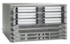
: Cisco ASR 1000 Series Aggregation Services Routers SIPs Figure 2-1 shows an example of a SIP installed on a Cisco ASR 1006 Router. The router has three chassis slots for SIPs, and can accommodate a total of twelve SPAs. Figure 2-1 SIP and SPAs Installed in a Cisco ASR 1006 Router Some commands - Cisco ASR1006 | Hardware Installation Guide - Page 33
a horizontal orientation, as shown in the "SIP and SPA Product Overview" chapter of the Cisco ASR 1000 Series Aggregation Services Routers SIP and SPA Software Configuration Guide. The Cisco ASR 1000 series SIP supports four subslots for the installation of SPAs. As shown in Figure 2-2, the subslot - Cisco ASR1006 | Hardware Installation Guide - Page 34
3d20h P0 ASR1006-PWR-AC ok 3d20h P1 ASR1006-FAN ok 3d20h Slot CPLD Version Firmware Version 0 07091401 12.2(33r)XN2 1 07091401 12.2(33r)XN2 2 07091401 12.2(33r)XN2 Cisco ASR 1000 Series Aggregation Services Routers SIP and SPA Hardware Installation Guide 2-6 OL-14126 - Cisco ASR1006 | Hardware Installation Guide - Page 35
Services Routers SIPs Cisco ASR 1000 Series SPA Interface Processor Overview R0 07082312 12.2(33r)XN2 The following is a show platform command output example displaying the status of the DSP SPA installed on a Cisco ASR 1000 Series Routers: Router# show platform Chassis type: ASR1004 Slot - Cisco ASR1006 | Hardware Installation Guide - Page 36
41.4 mm) x 16.725 inches (424.8 mm) x 14.187 inches (360.3 mm) Shipping weight 8.5 lb (3.9 kg) Operating temperature Nominal-40.9 to 104°F (5 to 40°C) Short Term-40.9 to 131°F (5 to 55°C) Cisco ASR 1000 Series Aggregation Services Routers SIP and SPA Hardware Installation Guide 2-8 OL-14126-12 - Cisco ASR1006 | Hardware Installation Guide - Page 37
to ESP-40 and then installing the ASR1000-SIP40 into the system. The following sections describe the Cisco ASR1000-SIP40: • Cisco ASR1000-SIP40 LEDs • Cisco ASR1000-SIP40 Physical Specifications OL-14126-12 Cisco ASR 1000 Series Aggregation Services Routers SIP and SPA Hardware Installation Guide - Cisco ASR1006 | Hardware Installation Guide - Page 38
. The Cisco ASR1000-SIP40 is loading. The Cisco ASR1000-SIP40 is online. The Cisco ASR1000-SIP40 is powered off. The Cisco ASR1000-SIP40 is powered on. The Cisco ASR1000-SIP40 is powered off. 2-10 Cisco ASR 1000 Series Aggregation Services Routers SIP and SPA Hardware Installation Guide OL-14126 - Cisco ASR1006 | Hardware Installation Guide - Page 39
Cisco ASR 1006 Router and Cisco ASR 1004 Router. Figure 2-5 Cisco ASR 1013 Router SPA Interface Slot Numbering Front of SIP, horizontal chassis slots SPA 0 SPA 2 SPA 1 SPA 3 231508 OL-14126-12 Cisco ASR 1000 Series Aggregation Services Routers SIP and SPA Hardware Installation Guide 2-11 - Cisco ASR1006 | Hardware Installation Guide - Page 40
ASR 1000 Series Aggregation Services Routers SIPs Figure 2-6 shows the slot numbering for the shared port adapters on the Cisco ASR 1013 Routers. Note The Cisco ASR1000-ESP10 and Cisco ASR1000-ESP20 will not plug into the Cisco ASR 1013 Router ESP slots. The Cisco ASR 1013 Router supports six SIP - Cisco ASR1006 | Hardware Installation Guide - Page 41
SIPs Cisco ASR 1000 Series SPA Interface Processor Overview 1 SPA-Slot 5 2 SPA-Slot 4 3 SPA-Slot 3 4 RP-2-R1 5 ESP-40-F1 6 RP-Filler-F0 7 RP-2-R0 8 SPA-Slot 2 9 SPA-Slot 1 10 SPA-Slot 0 OL-14126-12 Cisco ASR 1000 Series Aggregation Services Routers SIP and SPA Hardware Installation Guide - Cisco ASR1006 | Hardware Installation Guide - Page 42
Cisco ASR 1000 Series SPA Interface Processor Overview Chapter 2 Overview: Cisco ASR 1000 Series Aggregation Services Routers SIPs 2-14 Cisco ASR 1000 Series Aggregation Services Routers SIP and SPA Hardware Installation Guide OL-14126-12 - Cisco ASR1006 | Hardware Installation Guide - Page 43
page 3-48 • 1-Port OC-192c/STM-64 POS/RPR XFP SPA Overview, page 3-52 Serial SPAs • 4-Port and 8-Port Fast Ethernet SPA Overview, page 3-12 • 2-Port and 4-Port Channelized T3 Serial SPA Overview, page 3-57 Cisco ASR 1000 Series Aggregation Services Routers SIP and SPA Hardware Installation Guide 3-1 - Cisco ASR1006 | Hardware Installation Guide - Page 44
1.0 IOS XE 2.3 1 Cisco 1.0 IOS XE 2.5 4 Cisco 1.0 IOS XE 2.1 8 Cisco 1.0 IOS XE 2.1 1 Cisco 1.0 IOS XE 2.1 1 Cisco IOS XE 1.0 3.3.0S 2 Cisco 1.0 IOS XE 2.1 5 Cisco 1.0 IOS XE 2.1 Cisco ASR 1000 Series Aggregation Services Routers SIP and SPA Hardware Installation Guide - Cisco ASR1006 | Hardware Installation Guide - Page 45
1.0 IOS XE 2.2 1 Cisco 1.0 IOS XE 2.4 1 Cisco 1.0 IOS XE 2.2 1 Cisco 1.0 IOS XE 2.6 8 Cisco 1.0 IOS XE 2.1 2 Cisco 1.0 IOS XE 2.1 4 Cisco 1.0 IOS XE 2.1 2 Cisco 1.0 IOS XE 2.1 Cisco ASR 1000 Series Aggregation Services Routers SIP and SPA Hardware Installation Guide 3-3 - Cisco ASR1006 | Hardware Installation Guide - Page 46
of the router. Table 3-2 provides information about the bandwidth for each port (per-port bandwidth) on a SPA and the cumulative bandwidth (total bandwidth) for all ports available on the SPA. Cisco ASR 1000 Series Aggregation Services Routers SIP and SPA Hardware Installation Guide 3-4 OL-14126 - Cisco ASR1006 | Hardware Installation Guide - Page 47
4 2488.32 Mbps2 8 4976.64 Mbps3 1 2.488 Gbps 2 4976 Mbps 4 9.952 Mbps 1 10 Gbps 1 155.52 Mbps 1 622.08 Mbps 8 12.35 Mbps (T1) 16.38 Mbps (E1) 2 89.47 Mbps 4 178.94 Mbps OL-14126-12 Cisco ASR 1000 Series Aggregation Services Routers SIP and SPA Hardware Installation Guide 3-5 - Cisco ASR1006 | Hardware Installation Guide - Page 48
-height SPAs. The chassis models of the Cisco ASR 1000 Series Aggregation Services Routers support a different maximum number of SIPs as follows: • Cisco ASR 1002 and Cisco ASR1002-Fixed Routers - 1 embedded SIP • Cisco ASR 1004 Router - 2 SIPs • Cisco ASR 1006 Router - 3 SIPs Each Cisco ASR1000 - Cisco ASR1006 | Hardware Installation Guide - Page 49
96 ports Warning Double-wide SPAs are not supported on Cisco ASR1000-SIP40. The chassis models of the Cisco ASR 1000 Series Aggregation Services routers support a different maximum number of Cisco ASR1000-SIP40 as follows: • Cisco ASR 1006 Router - three SIPs • Cisco ASR 1013 Router - six SIPs - Cisco ASR1006 | Hardware Installation Guide - Page 50
and multimode optical fiber connection (see Figure 3-2). Each SPA port accepts an SFP module with a duplex LC-type receptacle that allows connection to single-mode or multimode optical fiber. Cisco ASR 1000 Series Aggregation Services Routers SIP and SPA Hardware Installation Guide 3-8 OL-14126-12 - Cisco ASR1006 | Hardware Installation Guide - Page 51
provides SONET and SDH network connectivity with a per-port bandwidth of 622.08 Mbps. For more information about SPA bandwidth, see the "Bandwidth Oversubscription" section in this chapter. OL-14126-12 Cisco ASR 1000 Series Aggregation Services Routers SIP and SPA Hardware Installation Guide 3-9 - Cisco ASR1006 | Hardware Installation Guide - Page 52
by software, and loopback is off. Port is enabled by software, and loopback is on. SPA power is off. SPA power is on and good, and SPA is being configured. SPA is ready and operational. 3-10 Cisco ASR 1000 Series Aggregation Services Routers SIP and SPA Hardware Installation Guide OL-14126-12 - Cisco ASR1006 | Hardware Installation Guide - Page 53
fiber (SONET STS-12c or SDH STM-4) Use a multimode optical fiber that has a core/cladding diameter of 62.5/125 microns. • Single-mode-622.08-Mbps, OC-12 optical fiber (SONET STS-12c or SDH STM-4) Cisco ASR 1000 Series Aggregation Services Routers SIP and SPA Hardware Installation Guide 3-11 - Cisco ASR1006 | Hardware Installation Guide - Page 54
Figure 3-7. Figure 3-7 8-Port Fast Ethernet SPA Faceplate 1 2 0 A/L 1 A/L 2 A/L 3 A/L 4 A/L 5 A/L 6 A/L 7 A/L STATUS SPA-8X1FE-TX-V2 1 A/L (Active/Link) LED 2 STATUS LED 138712 3-12 Cisco ASR 1000 Series Aggregation Services Routers SIP and SPA Hardware Installation Guide OL-14126 - Cisco ASR1006 | Hardware Installation Guide - Page 55
interference (EMI) and susceptibility to common-mode sources. Wire pairs 4/5 and 7/8 are actively terminated in the RJ-45 port circuitry in the 4-Port and 8-Port Fast Ethernet SPA. OL-14126-12 Cisco ASR 1000 Series Aggregation Services Routers SIP and SPA Hardware Installation Guide 3-13 - Cisco ASR1006 | Hardware Installation Guide - Page 56
the 1-Port 10-Gigabit Ethernet SPA: • 1-Port 10-Gigabit Ethernet SPA LEDs, page 3-15 • 1-Port 10-Gigabit Ethernet SPA XFP Optical Transceiver Modules, Connectors, and Cables, page 3-16 3-14 Cisco ASR 1000 Series Aggregation Services Routers SIP and SPA Hardware Installation Guide OL-14126 - Cisco ASR1006 | Hardware Installation Guide - Page 57
and the link is up. Port is enabled by software and the link is down. SPA power is off. SPA is ready and operational. SPA power is on and good, and the SPA is being configured. 246029 OL-14126-12 Cisco ASR 1000 Series Aggregation Services Routers SIP and SPA Hardware Installation Guide 3-15 - Cisco ASR1006 | Hardware Installation Guide - Page 58
and passes it to an output driver. See the label on the XFP module for technology type and model. Figure 3-14 shows an XFP module and Table 3-8 shows the XFP module specifications. 3-16 Cisco ASR 1000 Series Aggregation Services Routers SIP and SPA Hardware Installation Guide OL-14126-12 - Cisco ASR1006 | Hardware Installation Guide - Page 59
Chapter 3 Overview: Cisco ASR 1000 Series Aggregation Services Routers SPAs Figure 3-14 XFP Module 1-Port 10-Gigabit Ethernet SPA Overview 129499 Table 3-8 XFP Module Specifications for the 1-Port 10-Gigabit Ethernet SPA Specification Dimensions (H xWx L) Wavelength (TX) Cabling distance ( - Cisco ASR1006 | Hardware Installation Guide - Page 60
Color Off Green Amber Off State Off On On Off Meaning Port is not enabled. Port is enabled and the link is up. Port is enabled and the link is down. SPA power is off. STATUS 211969 3-18 Cisco ASR 1000 Series Aggregation Services Routers SIP and SPA Hardware Installation Guide OL-14126-12 - Cisco ASR1006 | Hardware Installation Guide - Page 61
unshielded twisted pair (UTP) RJ-45 cables; these cables are available commercially. Figure 3-16 shows the RJ-45 connector. Table 3-11 lists the pinouts and signals for the RJ-45 connector. OL-14126-12 Cisco ASR 1000 Series Aggregation Services Routers SIP and SPA Hardware Installation Guide 3-19 - Cisco ASR1006 | Hardware Installation Guide - Page 62
SPA Connectors, page 3-22 5-Port Gigabit Ethernet SPA LEDs The 5-Port Gigabit Ethernet SPA has two types of LEDs: an A/L LED for each port on the SPA, and one STATUS LED, as shown in Figure 3-17. 3-20 Cisco ASR 1000 Series Aggregation Services Routers SIP and SPA Hardware Installation Guide - Cisco ASR1006 | Hardware Installation Guide - Page 63
SPAs 5-Port Gigabit Ethernet SPA Overview Figure 3-17 5-Port Gigabit Ethernet SPA Faceplate 1 2 A/L A/L A/L A/L A/L STATUS 1 A/L (Active/Link) LED 2 STATUS LED SPA-5X1GE-V2 129106 OL-14126-12 Cisco ASR 1000 Series Aggregation Services Routers SIP and SPA Hardware Installation Guide - Cisco ASR1006 | Hardware Installation Guide - Page 64
Gigabit Ethernet SPA Overview The following sections describe the 8-port Gigabit Ethernet SPA: • 8-Port Gigabit Ethernet SPA LEDs, page 3-23 • 8-Port Gigabit Ethernet SPA Connectors, page 3-23 3-22 Cisco ASR 1000 Series Aggregation Services Routers SIP and SPA Hardware Installation Guide OL-14126 - Cisco ASR1006 | Hardware Installation Guide - Page 65
and for products other than the 8-Port Gigabit Ethernet SPA. However, the information in this document pertains only to SFP modules that plug into the 8-Port Gigabit Ethernet SPA ports. OL-14126-12 Cisco ASR 1000 Series Aggregation Services Routers SIP and SPA Hardware Installation Guide 3-23 - Cisco ASR1006 | Hardware Installation Guide - Page 66
Label A/L STATUS Color Off Green Amber Off State Off On On Off Meaning Port is not enabled. Port is enabled and the link is up. Port is enabled and the link is down. SPA power is off. 3-24 Cisco ASR 1000 Series Aggregation Services Routers SIP and SPA Hardware Installation Guide OL-14126-12 - Cisco ASR1006 | Hardware Installation Guide - Page 67
port (RX) and a transmitter port (TX) that compose one optical interface. Table 3-15, Table 3-16, Table 3-17, Table 3-18, and Table 3-19 provide SFP module information and specifications. OL-14126-12 Cisco ASR 1000 Series Aggregation Services Routers SIP and SPA Hardware Installation Guide - Cisco ASR1006 | Hardware Installation Guide - Page 68
-LX/LH SFP transceiver module The 1000BASE-LX/LH SFP transceiver module is DOM capable, and operates on singlemode fiber-optic (SMF) of up to 10-Km link length with 1310 nm wavelength. 3-26 Cisco ASR 1000 Series Aggregation Services Routers SIP and SPA Hardware Installation Guide OL-14126-12 - Cisco ASR1006 | Hardware Installation Guide - Page 69
fiber. (Premium single-mode fiber has a lower attenuation per unit length than ordinary single-mode fiber; dispersion-shifted single-mode fiber has both lower attenuation and less dispersion.) OL-14126-12 Cisco ASR 1000 Series Aggregation Services Routers SIP and SPA Hardware Installation Guide - Cisco ASR1006 | Hardware Installation Guide - Page 70
- Maximum Cable Distance 722 ft (220 m) 984 ft (300 m) 1640 ft (500 m) 1804 ft (550 m) 1804 ft (550 m) 1804 ft (550 m) 1804 ft (550 m) 6.2 miles (10 km) 3-28 Cisco ASR 1000 Series Aggregation Services Routers SIP and SPA Hardware Installation Guide OL-14126-12 - Cisco ASR1006 | Hardware Installation Guide - Page 71
CWDM Module Color Cisco CWDM 1470-nm SFP module; Gigabit Ethernet and Gray 1- and 2-Gb Fibre Channel Cisco CWDM 1490-nm SFP module; Gigabit Ethernet and Violet 1- and 2-Gb Fibre Channel OL-14126-12 Cisco ASR 1000 Series Aggregation Services Routers SIP and SPA Hardware Installation Guide 3-29 - Cisco ASR1006 | Hardware Installation Guide - Page 72
2-Gb Fibre Channel Cisco CWDM 1590-nm SFP module; Gigabit Ethernet and Red 1- and 2-Gb Fibre Channel Cisco CWDM 1610-nm SFP module; Gigabit Ethernet and Brown 1- and 2-Gb Fibre Channel 3-30 Cisco ASR 1000 Series Aggregation Services Routers SIP and SPA Hardware Installation Guide OL-14126-12 - Cisco ASR1006 | Hardware Installation Guide - Page 73
ITU grid) 1000BASE-DWDM 1532.68 nm SFP module (100-GHz ITU grid) ITU Channel 21 22 23 24 26 27 28 29 31 32 33 34 36 37 38 39 41 42 43 44 46 47 48 49 51 52 53 54 56 OL-14126-12 Cisco ASR 1000 Series Aggregation Services Routers SIP and SPA Hardware Installation Guide 3-31 - Cisco ASR1006 | Hardware Installation Guide - Page 74
. Green Port is enabled by the software, and the link is valid. Amber and This state is unused and its meaning is undefined. green Debug LED Green Indicates a SPA OK status to the host. 3-32 Cisco ASR 1000 Series Aggregation Services Routers SIP and SPA Hardware Installation Guide OL-14126 - Cisco ASR1006 | Hardware Installation Guide - Page 75
support Interface Type and Density Local Timing Interfaces Local Timing Frequency BITS Interface Support SSM Support Description Yes 2x1 GE Input; Output 1.544 MHz / 2.048 MHz In; Out Yes OL-14126-12 Cisco ASR 1000 Series Aggregation Services Routers SIP and SPA Hardware Installation Guide - Cisco ASR1006 | Hardware Installation Guide - Page 76
21 SFP Optics Module 127158 Long-range SFP optical transceiver modules (for long-reach configurations) cannot be connected back-to-back without using an attenuator between the two of them. 3-34 Cisco ASR 1000 Series Aggregation Services Routers SIP and SPA Hardware Installation Guide OL-14126 - Cisco ASR1006 | Hardware Installation Guide - Page 77
. Figure 3-22 4-Port OC-3c/STM-1 POS SPA Faceplate 1 STATUS 122938 C/A A/L 0 C/A A/L 1 C/A A/L 2 C/A A/L 3 2 3 1 C/A (Carrier/Alarm) LED 2 A/L (Active/Loopback) LED 3 STATUS LED OL-14126-12 Cisco ASR 1000 Series Aggregation Services Routers SIP and SPA Hardware Installation Guide 3-35 - Cisco ASR1006 | Hardware Installation Guide - Page 78
-reach (SR) SFP module-SFP-OC3-SR • Intermediate-reach (IR) SFP module (15 km)-SFP-OC3-IR1 • Long-reach (LR) SFP module (40 km)-SFP-OC3-LR1 • Long-reach (LR) SFP module (80 km)-SFP-OC3-LR2 3-36 Cisco ASR 1000 Series Aggregation Services Routers SIP and SPA Hardware Installation Guide OL-14126-12 - Cisco ASR1006 | Hardware Installation Guide - Page 79
transceiver modules (for long-reach configurations) cannot be connected back-to-back without using an attenuator between them. Figure 3-24 LC-Type Cables / / / / / / RX TX 84929 OL-14126-12 Cisco ASR 1000 Series Aggregation Services Routers SIP and SPA Hardware Installation Guide 3-37 - Cisco ASR1006 | Hardware Installation Guide - Page 80
Overview The 1-Port OC-48c/STM-16 POS SPA provides Packet over SONET (POS) network connectivity with a bandwidth of 9.95 Gbps. The following sections describe the 1-Port OC-48c/STM-16 POS SPA: 3-38 Cisco ASR 1000 Series Aggregation Services Routers SIP and SPA Hardware Installation Guide OL-14126 - Cisco ASR1006 | Hardware Installation Guide - Page 81
. Mate port is synchronized. Port is not enabled by software. Port is enabled by software. Port is enabled by software, and there is at least one alarm. Port is not enabled by software. OL-14126-12 Cisco ASR 1000 Series Aggregation Services Routers SIP and SPA Hardware Installation Guide 3-39 - Cisco ASR1006 | Hardware Installation Guide - Page 82
at OC-48c/STM-64 line rates (9.95 Gbps). Packet data is transported with a user-configured encapsulation (such as Point-to-Point Protocol [PPP]), and is mapped into the STS-48/STM-64 frame. 3-40 Cisco ASR 1000 Series Aggregation Services Routers SIP and SPA Hardware Installation Guide OL-14126-12 - Cisco ASR1006 | Hardware Installation Guide - Page 83
3-42 • 2-Port and 4-Port OC-48c/STM-16 POS SPA Interface Specifications, page 3-43 • 2-Port and 4-Port OC-48c/STM-16 POS SPA Cables, Optical Transceiver Modules, and Connectors, page 3-43 OL-14126-12 Cisco ASR 1000 Series Aggregation Services Routers SIP and SPA Hardware Installation Guide 3-41 - Cisco ASR1006 | Hardware Installation Guide - Page 84
wrapped. Flashing Port is locally steering. Off Port is not enabled by software. On Port is enabled by software, and loopback is off. On Port is enabled by software, and loopback is on. 3-42 Cisco ASR 1000 Series Aggregation Services Routers SIP and SPA Hardware Installation Guide OL-14126 - Cisco ASR1006 | Hardware Installation Guide - Page 85
use either a duplex LC-type cable (see Figure 3-28) or two simplex LC-type cables, one for transmit (TX) and one for receive (RX). Figure 3-28 LC-Type Cables / / / / / / RX TX 84929 OL-14126-12 Cisco ASR 1000 Series Aggregation Services Routers SIP and SPA Hardware Installation Guide 3-43 - Cisco ASR1006 | Hardware Installation Guide - Page 86
-10 Modules and Cables, page 3-46 1-Port OC-12c/STM-4 POS SPA LEDs The 1-Port OC-12c/STM-4 POS SPA has three types of LEDs: two LEDs for each port on the SPA, and one STATUS LED, as shown in Figure 3-29. 3-44 Cisco ASR 1000 Series Aggregation Services Routers SIP and SPA Hardware Installation Guide - Cisco ASR1006 | Hardware Installation Guide - Page 87
-based Internets • RFC 1156, Management Information Base for Network Management of TCP/IP-Based Internets • RFC 1157, Simple Network Management Protocol (SNMP) OL-14126-12 Cisco ASR 1000 Series Aggregation Services Routers SIP and SPA Hardware Installation Guide 3-45 - Cisco ASR1006 | Hardware Installation Guide - Page 88
SPA-equipped routers back-to-back. Long-range SFP optical transceiver modules (for long-reach configurations) cannot be connected back-to-back without using an attenuator between the two of them. 3-46 Cisco ASR 1000 Series Aggregation Services Routers SIP and SPA Hardware Installation Guide OL - Cisco ASR1006 | Hardware Installation Guide - Page 89
: -26 dBm OC-12 SR: -23 dBm OC-12 IR-1: -28 dBm OC-12 LR-1: -28 dBm OC-12 LR-2: -28 dBm OL-14126-12 Cisco ASR 1000 Series Aggregation Services Routers SIP and SPA Hardware Installation Guide 3-47 - Cisco ASR1006 | Hardware Installation Guide - Page 90
Three different faceplates exist for the 2-Port, 4-Port, and 8-Port OC-12c/STM-4 Multirate POS SPAs. They each contain the same LEDs and the number of ports are 2, 4, and 8 respectively. 3-48 Cisco ASR 1000 Series Aggregation Services Routers SIP and SPA Hardware Installation Guide OL-14126-12 - Cisco ASR1006 | Hardware Installation Guide - Page 91
POS SPA interface complies with the following IETF RFCs: • RFC 1662, PPP in HDLC-like Framing • RFC 2427, Multiprotocol Interconnect over Frame Relay Encapsulation • RFC 2615, PPP over SONET/SDH OL-14126-12 Cisco ASR 1000 Series Aggregation Services Routers SIP and SPA Hardware Installation Guide - Cisco ASR1006 | Hardware Installation Guide - Page 92
-equipped routers back-to-back. Long-range SFP optical transceiver modules (for long-reach configurations) cannot be connected back-to-back without using an attenuator between the two of them. 3-50 Cisco ASR 1000 Series Aggregation Services Routers SIP and SPA Hardware Installation Guide OL-14126 - Cisco ASR1006 | Hardware Installation Guide - Page 93
: -26 dB OC-12 SR: -23 dBm OC-12 IR-1: -28 dBm OC-12 LR-1: -28 dBm OC-12 LR-2: -28 dBm OL-14126-12 Cisco ASR 1000 Series Aggregation Services Routers SIP and SPA Hardware Installation Guide 3-51 - Cisco ASR1006 | Hardware Installation Guide - Page 94
13 4 2 5 WPARSASPMT HART EUS Y N C C A R R I EARC T I V E SPA-0C192POS-XFP 6 0 STATUS 129432 1 WRAP LED 2 PASSTHRU LED 3 MATESYNC LED 4 CARRIER LED 5 ACTIVE LED 6 STATUS LED 3-52 Cisco ASR 1000 Series Aggregation Services Routers SIP and SPA Hardware Installation Guide OL-14126-12 - Cisco ASR1006 | Hardware Installation Guide - Page 95
1-Port OC-192c/STM-64 POS/RPR XFP SPA uses a single-mode, 9.95 Gbps, OC-192c optical fiber (SONET STS-192c or SDH STM-64) optical transceiver module for SONET and SDH connection to the network. OL-14126-12 Cisco ASR 1000 Series Aggregation Services Routers SIP and SPA Hardware Installation Guide - Cisco ASR1006 | Hardware Installation Guide - Page 96
-192 IR-2: -1 dBm +2 dBm OC-192 LR-2: 0 to +4 dBm OC-192 SR-1: -11 dBm OC-192 IR-2: -14 dBm OC-192 LR-2: -24 dBm 3-54 Cisco ASR 1000 Series Aggregation Services Routers SIP and SPA Hardware Installation Guide OL-14126-12 - Cisco ASR1006 | Hardware Installation Guide - Page 97
C/A A/L 2 TX RX C/A A/L TX 3 STATUS RX SPA-4XT3/E3 5 1 C/A (Carrier/Alarm) LED 2 A/L (Active/Loopback) LED 3 TX (Transmit) connector 4 RX (Receive) connector 5 STATUS LED 203209 OL-14126-12 Cisco ASR 1000 Series Aggregation Services Routers SIP and SPA Hardware Installation Guide 3-55 - Cisco ASR1006 | Hardware Installation Guide - Page 98
-Female, 10 feet) • CAB-T3E3-RF-OPEN (T3 or E3 Cable, 1.0/2.3 RF to BNC-Open end, 10 feet) Note The Cisco cable part numbers are 72-4124-01 (with male BNC end) and 72-4131-01 (with female BNC end). 3-56 Cisco ASR 1000 Series Aggregation Services Routers SIP and SPA Hardware Installation Guide OL - Cisco ASR1006 | Hardware Installation Guide - Page 99
1 TX RX C/A A/L 2 TX RX C/A A/L 3 TX RSX PA-4XCT3/DS0 5 1 C/A (Carrier/Alarm) LED 2 A/L (Active/Loopback) LED 3 TX (Transmit) connector 4 RX (Receive) connector 5 STATUS LED OL-14126-12 Cisco ASR 1000 Series Aggregation Services Routers SIP and SPA Hardware Installation Guide 3-57 - Cisco ASR1006 | Hardware Installation Guide - Page 100
-Female, 10 feet) • CAB-T3E3-RF-OPEN (T3 or E3 Cable, 1.0/2.3 RF to BNC-Open end, 10 feet) Note The Cisco cable part numbers are 72-4124-01 (with Male BNC end) and 72-4131-01 (with Female BNC end). 3-58 Cisco ASR 1000 Series Aggregation Services Routers SIP and SPA Hardware Installation Guide OL - Cisco ASR1006 | Hardware Installation Guide - Page 101
1 2 3 ACTIVE 0 CD/ LB ACTIVE 1 CD/ LB ACTIVE 2 CD/ LB ACTIVE 3 CD/ LB STATUS SPA-4XT-SERIAL 1 ACTIVE LED 2 CD/LB (Carrier Detect/Loopback) LED 3 STATUS LED 250158 OL-14126-12 Cisco ASR 1000 Series Aggregation Services Routers SIP and SPA Hardware Installation Guide 3-59 - Cisco ASR1006 | Hardware Installation Guide - Page 102
is not complete). 4-Port Serial Interface SPA Interface Specifications The 4-Port Serial Interface SPA supports six interfaces in DCE and DTE mode: • V.35 • EIA/TIA-232 • EIA/TIA-449 3-60 Cisco ASR 1000 Series Aggregation Services Routers SIP and SPA Hardware Installation Guide OL-14126-12 - Cisco ASR1006 | Hardware Installation Guide - Page 103
10 feet (3 meters) X.21 DCE 10 feet (3 meters) EIA/TIA-530 DTE 10 feet (3 meters) EIA/TIA-530A DTE 10 feet (3 meters) Connector Type Male Female Male Female Male Female Male Female Male Male OL-14126-12 Cisco ASR 1000 Series Aggregation Services Routers SIP and SPA Hardware Installation Guide - Cisco ASR1006 | Hardware Installation Guide - Page 104
+ 18 I_RXD/TXD- 6 B_DCD/DCD+ 19 B_DCD/DCD- 7 O_DTR/DSR+ 20 O_DTR/DSR- 8 O_RTS/CTS+ 21 MODE2 9 O_RTS/CTS- 22 MODE1 10 I_CTS/RTS- 23 MODE0 11 I_CTS/RTS+ 24 MODEDCE 3-62 Cisco ASR 1000 Series Aggregation Services Routers SIP and SPA Hardware Installation Guide OL-14126-12 - Cisco ASR1006 | Hardware Installation Guide - Page 105
by software. Port is enabled by software, and there is a valid T1 or E1 signal without any alarms. Port is enabled by software, and there is at least one alarm. SPA-8XCHT1/E1 STATUS 116852 OL-14126-12 Cisco ASR 1000 Series Aggregation Services Routers SIP and SPA Hardware Installation Guide 3-63 - Cisco ASR1006 | Hardware Installation Guide - Page 106
-45 Connector Pinouts Pin Signal 1 RX- 2 RX+ 3 NC 4 TX- 5 TX+ 6 NC Description Receive ring - Receive tip + No connection Transmit ring - Transmit tip + No connection 3-64 Cisco ASR 1000 Series Aggregation Services Routers SIP and SPA Hardware Installation Guide OL-14126-12 - Cisco ASR1006 | Hardware Installation Guide - Page 107
: • 1-Port Channelized STM-1/OC-3 SPA LEDs, page 3-66 • 1-Port Channelized STM-1/OC-3 SPA Interface Specifications, page 3-66 • 1-Port Channelized STM-1/OC-3 SPA Cables and Connectors, page 3-67 OL-14126-12 Cisco ASR 1000 Series Aggregation Services Routers SIP and SPA Hardware Installation Guide - Cisco ASR1006 | Hardware Installation Guide - Page 108
at OC-3c/STM-1 line rates (155.52 Mbps). Packet data is transported with a user-configured encapsulation (such as Point-to-Point Protocol [PPP]), and is mapped into the STS-3c/STM-1 frame. 3-66 Cisco ASR 1000 Series Aggregation Services Routers SIP and SPA Hardware Installation Guide OL-14126-12 - Cisco ASR1006 | Hardware Installation Guide - Page 109
SPA-equipped routers back-to-back. Long-range SFP optical transceiver modules (for long-reach configurations) cannot be connected back-to-back without using an attenuator between the two of them. OL-14126-12 Cisco ASR 1000 Series Aggregation Services Routers SIP and SPA Hardware Installation Guide - Cisco ASR1006 | Hardware Installation Guide - Page 110
2 280921 C/A A/L 3 STATUS SPA-1XCHOC12/DS0 1 C/A (Carrier/Alarm) LED 2 A/L (Active/Loopback) LED 3 STATUS LED The 1-Port Channelized OC-12/STM-4 SPA LEDs are described in Table 3-43. 3-68 Cisco ASR 1000 Series Aggregation Services Routers SIP and SPA Hardware Installation Guide OL-14126-12 - Cisco ASR1006 | Hardware Installation Guide - Page 111
/STM-4 SPA uses a small form-factor pluggable (SFP) optical transceiver module installed in each port for SONET and SDH single-mode and multimode optical fiber connection (see Figure 3-47). OL-14126-12 Cisco ASR 1000 Series Aggregation Services Routers SIP and SPA Hardware Installation Guide 3-69 - Cisco ASR1006 | Hardware Installation Guide - Page 112
transceiver modules (for long-reach configurations) cannot be connected back-to-back without using an attenuator between the two of them. Figure 3-48 LC Type Cables / / / / / / RX TX 84929 3-70 Cisco ASR 1000 Series Aggregation Services Routers SIP and SPA Hardware Installation Guide OL - Cisco ASR1006 | Hardware Installation Guide - Page 113
SPA Front Shutdown Button and LEDs LED Label Shutdown Button Color State Meaning A recessed button that can shut down the system. This is an alternate method to using the shutdown command. OL-14126-12 Cisco ASR 1000 Series Aggregation Services Routers SIP and SPA Hardware Installation Guide - Cisco ASR1006 | Hardware Installation Guide - Page 114
in conjunction with the Session Border Controller (SBC) application to provide voice transcoding capabilities. The SPA-DSP can be installed in either SIP-10 or SIP-40 in any of the slots. 3-72 Cisco ASR 1000 Series Aggregation Services Routers SIP and SPA Hardware Installation Guide OL-14126-12 - Cisco ASR1006 | Hardware Installation Guide - Page 115
Product ID) SPA-DSP ASR1000 Router Route Chassis Processor Supported Supported ASR 1002, ASR 1004, and ASR 1006 Chassis RP1 and RP2 Power SIPs ESPs Requirements Supported Supported 25 watts SIP-10 and SIP-40 ESP-10 and ESP-40 Minimum Cisco IOS XE Release Supported Cisco IOS XE Release - Cisco ASR1006 | Hardware Installation Guide - Page 116
SPA-DSP LED SPA-DSPs have only one type of LED, which is the STATUS LED type, as shown in Figure 3-50. Figure 3-50 SPA-DSP Faceplate 1 STATUS 249811 1 STATUS LED Table 3-48 describes the SPA-DSP LED. 3-74 Cisco ASR 1000 Series Aggregation Services Routers SIP and SPA Hardware Installation Guide - Cisco ASR1006 | Hardware Installation Guide - Page 117
0 2 3 STATUS SPA-1CHOC3-CE-ATM CLASS 1 LASER SPA-1CHOC3CE-ATM 47-18493-XX REVXX VID: XXXXXXX CSA: XXXXXXX 1 C/A (Carrier/Alarm) LED 2 A/L (Active/Loopback) LED 3 STATUS LED 230029 OL-14126-12 Cisco ASR 1000 Series Aggregation Services Routers SIP and SPA Hardware Installation Guide 3-75 - Cisco ASR1006 | Hardware Installation Guide - Page 118
)-SFP-OC3-SR • Intermediate-Reach (IR) SFP module (15 km)-SFP-OC3-IR1 • Long-Reach (LR) SFP module (40 km)-SFP-OC3-LR1 • Long-Reach 2 (LR2) or Extended Reach SFP module (80 km)-SFP-OC3-LR2 3-76 Cisco ASR 1000 Series Aggregation Services Routers SIP and SPA Hardware Installation Guide OL-14126-12 - Cisco ASR1006 | Hardware Installation Guide - Page 119
Port is enabled by software, loopback is off. Port is enabled by software, loopback is on. SPA power is off. SPA power is on and the SPA is being configured. SPA is ready and operational. 250287 OL-14126-12 Cisco ASR 1000 Series Aggregation Services Routers SIP and SPA Hardware Installation Guide - Cisco ASR1006 | Hardware Installation Guide - Page 120
The Cisco cable part numbers are 72-4124-01 (for the male BNC end) and 72-4131-01 (for the female BNC end). A SPA can receive data over the cable up to a maximum distance of 1350 ft (411.5 meters). 3-78 Cisco ASR 1000 Series Aggregation Services Routers SIP and SPA Hardware Installation Guide OL - Cisco ASR1006 | Hardware Installation Guide - Page 121
SPA Faceplate SPA-24CHT1CE-ATM STATUS 254922 TX / RX B1 A C 0 1 2 3 4 5 6 7 8 9 10 11 A C 12 13 14 15 16 17 18 19 20 21 22 23 1 A/C (Alarm/Carrier) LEDs 1 2 2 STATUS LED OL-14126-12 Cisco ASR 1000 Series Aggregation Services Routers SIP and SPA Hardware Installation Guide 3-79 - Cisco ASR1006 | Hardware Installation Guide - Page 122
CEoP SPA requires a Cisco cable (part number CABLE-24T1E1J1), which is shown in Figure 3-54. Figure 3-54 24-Port Channelized T1/E1/J1 CEoP SPA High-Density Cable 1 51 50 100 50 26 25 1 250106 3-80 Cisco ASR 1000 Series Aggregation Services Routers SIP and SPA Hardware Installation Guide - Cisco ASR1006 | Hardware Installation Guide - Page 123
27 Not connected 77 4 3 54 28 28 Not connected 78 RX Cable Lead Not connected 1 26 Not connected 2 27 Not connected 3 28 OL-14126-12 Cisco ASR 1000 Series Aggregation Services Routers SIP and SPA Hardware Installation Guide 3-81 - Cisco ASR1006 | Hardware Installation Guide - Page 124
connected 4 29 Not connected 5 30 Not connected 6 31 Not connected 7 32 Not connected 8 33 Not connected 9 34 Not connected 10 35 Not connected 11 36 Not connected 12 37 Not connected 13 38 3-82 Cisco ASR 1000 Series Aggregation Services Routers SIP and SPA Hardware Installation Guide OL-14126-12 - Cisco ASR1006 | Hardware Installation Guide - Page 125
Overview: Cisco ASR 1000 Series Aggregation Services Routers SPAs 24-Port Channelized T1/E1/J1 ATM CEoP SPA Overview Table 3-53 24-Port Channelized T1/E1/J1 CEoP SPA Cable Connector 48 OL-14126-12 Cisco ASR 1000 Series Aggregation Services Routers SIP and SPA Hardware Installation Guide 3-83 - Cisco ASR1006 | Hardware Installation Guide - Page 126
accessory component for the Cisco PID SPA-24CHT1-CE-ATM. You can view the image of patch panel with the DCC2484/25T1-S part number at: http://www.occfiber.com/main/index.php?m=1&p=2&s=Y&l=en&it=54&i=193 3-84 Cisco ASR 1000 Series Aggregation Services Routers SIP and SPA Hardware Installation Guide - Cisco ASR1006 | Hardware Installation Guide - Page 127
Chapter 3 Overview: Cisco ASR 1000 Series Aggregation Services Routers SPAs 24-Port Channelized T1/E1/J1 ATM CEoP SPA Overview OL-14126-12 Cisco ASR 1000 Series Aggregation Services Routers SIP and SPA Hardware Installation Guide 3-85 - Cisco ASR1006 | Hardware Installation Guide - Page 128
24-Port Channelized T1/E1/J1 ATM CEoP SPA Overview Chapter 3 Overview: Cisco ASR 1000 Series Aggregation Services Routers SPAs 3-86 Cisco ASR 1000 Series Aggregation Services Routers SIP and SPA Hardware Installation Guide OL-14126-12 - Cisco ASR1006 | Hardware Installation Guide - Page 129
wiring. Safety Warnings Safety warnings appear throughout this publication in procedures that, if performed incorrectly, might harm you. A warning symbol precedes each warning statement. OL-14126-12 Cisco ASR 1000 Series Aggregation Services Routers SIP and SPA Hardware Installation Guide 4-1 - Cisco ASR1006 | Hardware Installation Guide - Page 130
qui accompagnent cet appareil, référez-vous au numéro de l'instruction situé à la fin de chaque avertissement. CONSERVEZ CES INFORMATIONS Warnung . BEWAHREN SIE DIESE HINWEISE GUT AUF. Cisco ASR 1000 Series Aggregation Services Routers SIP and SPA Hardware Installation Guide 4-2 OL-14126-12 - Cisco ASR1006 | Hardware Installation Guide - Page 131
Chapter 4 Preparing to Install a SIP or a SPA Safety Guidelines Avvertenza IMPORTANTI ISTRUZIONI SULLA SICUREZZA Questo som medföljer denna anordning. SPARA DESSA ANVISNINGAR OL-14126-12 Cisco ASR 1000 Series Aggregation Services Routers SIP and SPA Hardware Installation Guide 4-3 - Cisco ASR1006 | Hardware Installation Guide - Page 132
Safety Guidelines Chapter 4 Preparing to Install a SIP or a SPA Cisco ASR 1000 Series Aggregation Services Routers SIP and SPA Hardware Installation Guide 4-4 OL-14126-12 - Cisco ASR1006 | Hardware Installation Guide - Page 133
Chapter 4 Preparing to Install a SIP or a SPA Safety Guidelines OL-14126-12 Cisco ASR 1000 Series Aggregation Services Routers SIP and SPA Hardware Installation Guide 4-5 - Cisco ASR1006 | Hardware Installation Guide - Page 134
ports regardless of whether power to the unit is OFF or ON. To avoid electric shock, use caution when working near WAN ports. When detaching cables, detach the end when servicing. Statement 1034 Cisco ASR 1000 Series Aggregation Services Routers SIP and SPA Hardware Installation Guide 4-6 OL-14126- - Cisco ASR1006 | Hardware Installation Guide - Page 135
the housing is open, or both. Statement 1043 Warning The covers are an integral part of the safety design of the product. Do not operate the unit without the covers installed. Statement 1077 OL-14126-12 Cisco ASR 1000 Series Aggregation Services Routers SIP and SPA Hardware Installation Guide 4-7 - Cisco ASR1006 | Hardware Installation Guide - Page 136
captive installation screws to release the bus connectors from the backplane or midplane. • Handle carriers by available handles or edges only; avoid touching the printed circuit boards or connectors. Cisco ASR 1000 Series Aggregation Services Routers SIP and SPA Hardware Installation Guide 4-8 OL - Cisco ASR1006 | Hardware Installation Guide - Page 137
. Statement 1027 Warning Invisible laser radiation may be emitted from disconnected fibers or connectors. Do not stare into beams or view directly with optical instruments. Statement 1051 OL-14126-12 Cisco ASR 1000 Series Aggregation Services Routers SIP and SPA Hardware Installation Guide 4-9 - Cisco ASR1006 | Hardware Installation Guide - Page 138
Laser/LED Safety Chapter 4 Preparing to Install a SIP or a SPA 4-10 Cisco ASR 1000 Series Aggregation Services Routers SIP and SPA Hardware Installation Guide OL-14126-12 - Cisco ASR1006 | Hardware Installation Guide - Page 139
(EMI) emissions requirements and to allow proper airflow across the installed modules. If you plan to install a SIP in a slot that is not in use, you must first remove the blank filler plate. OL-14126-12 Cisco ASR 1000 Series Aggregation Services Routers SIP and SPA Hardware Installation Guide 5-1 - Cisco ASR1006 | Hardware Installation Guide - Page 140
"Setting input bandwidth to ESI max bandwidth: 11199896" is displayed on the console. This message is displayed when SIP-40 is downgraded to SIP-10 from Cisco IOS XE Release 3.1.0S onwards. Cisco ASR 1000 Series Aggregation Services Routers SIP and SPA Hardware Installation Guide 5-2 OL-14126-12 - Cisco ASR1006 | Hardware Installation Guide - Page 141
SIP in the specified slot and its installed SPAs, where: • slot-number-Specifies the SIP chassis slot number where the SIP is installed. • start-Activates the SIP and removes it from reset mode. OL-14126-12 Cisco ASR 1000 Series Aggregation Services Routers SIP and SPA Hardware Installation Guide - Cisco ASR1006 | Hardware Installation Guide - Page 142
Cisco ASR 1000-SIP10 installed in slot 0 and Cisco ASR1000-SIP40 installed in slots 1,2,3, and 4 of the Cisco ASR 1013 Router: Router# show platform Chassis type: ASR1013 Slot Type State Insert time (ago) Cisco ASR 1000 Series Aggregation Services Routers SIP and SPA Hardware Installation Guide - Cisco ASR1006 | Hardware Installation Guide - Page 143
ASR 1000 Series Routers support the removal of the SPA without deactivating it first. Before deactivating a SPA, ensure that the SIP is seated securely in the slot before you pull out the SPA. OL-14126-12 Cisco ASR 1000 Series Aggregation Services Routers SIP and SPA Hardware Installation Guide - Cisco ASR1006 | Hardware Installation Guide - Page 144
to use the hw-module subslot stop command in EXEC mode, you cause the SPA to gracefully shut down. However, the SPA will come up again when executing the hw-module subslot start command. Cisco ASR 1000 Series Aggregation Services Routers SIP and SPA Hardware Installation Guide 5-6 OL-14126-12 - Cisco ASR1006 | Hardware Installation Guide - Page 145
a SPA using the hw-module subslot stop command and need to reactivate it without performing an OIR, you must use the hw-module subslot start command to reactivate the SPA and its interfaces. OL-14126-12 Cisco ASR 1000 Series Aggregation Services Routers SIP and SPA Hardware Installation Guide 5-7 - Cisco ASR1006 | Hardware Installation Guide - Page 146
to perform OIR of the SIP. The following example deactivates the SIP that is installed in slot 1 of the Cisco ASR 1000 Series Router, its SPAs, and all of the interfaces: Router(config)# hw-module slot 1 stop Cisco ASR 1000 Series Aggregation Services Routers SIP and SPA Hardware Installation Guide - Cisco ASR1006 | Hardware Installation Guide - Page 147
SPA Configuration Example Deactivate a SPA when you want to perform OIR of that SPA. The following example deactivates the SPA (and its interfaces) that is installed in subslot 0 of the SIP located in slot 1 of the Cisco ASR 1000 Series Router and removes power to the SPA. Router(config)# hw-module - Cisco ASR1006 | Hardware Installation Guide - Page 148
locking thumbscrews on both sides of the SIP. Slide the SIP out of the router slot. If you are removing a blank filler plate, pull the blank filler plate completely out of the router slot. 5-10 Cisco ASR 1000 Series Aggregation Services Routers SIP and SPA Hardware Installation Guide OL-14126-12 - Cisco ASR1006 | Hardware Installation Guide - Page 149
PWR STATUS 0 1 3 1 3 ASR1000-SIP10 PWR STATUS 1 3 ASR1000-SIP10G ASR1000-SIP10G 0 2 3 1 2 ASR1000-SIP10G 0 3 231540 ASR1000-SIP10G 0 1 Captive installation screw 2 Guide rails OL-14126-12 Cisco ASR 1000 Series Aggregation Services Routers SIP and SPA Hardware Installation Guide - Cisco ASR1006 | Hardware Installation Guide - Page 150
SIP Installation and Removal Chapter 5 Installing and Removing a SIP 5-12 Cisco ASR 1000 Series Aggregation Services Routers SIP and SPA Hardware Installation Guide OL-14126-12 - Cisco ASR1006 | Hardware Installation Guide - Page 151
(EMI) emissions requirements and to allow proper airflow across the SPAs. If you plan to install a SPA in a subslot that is not in use, you must first remove the SPA blank filler plate. OL-14126-12 Cisco ASR 1000 Series Aggregation Services Routers SIP and SPA Hardware Installation Guide 6-1 - Cisco ASR1006 | Hardware Installation Guide - Page 152
important information about SPA cable clips that will help to make removing the SPA easier. The SPA accessory kit is shipped with three different versions of cable clips, as shown in Figure 6-3. Cisco ASR 1000 Series Aggregation Services Routers SIP and SPA Hardware Installation Guide 6-2 OL-14126 - Cisco ASR1006 | Hardware Installation Guide - Page 153
with the SPA) To install a cable clip to each side of the SPA, follow these steps: Step 1 Select one set of cable clips from the SPA accessory kit. Figure 6-3 shows the cable clip options. OL-14126-12 Cisco ASR 1000 Series Aggregation Services Routers SIP and SPA Hardware Installation Guide 6-3 - Cisco ASR1006 | Hardware Installation Guide - Page 154
6-4. Figure 6-4 Installing a Cisco ASR 1000 Series Cable Clip into the SPA Plastic Pull Tab 2 1 1 3 1 Portion of the cable clip that locks into position 2 SPA plastic pull tab 3 SPA Cisco ASR 1000 Series Aggregation Services Routers SIP and SPA Hardware Installation Guide 6-4 275931 OL - Cisco ASR1006 | Hardware Installation Guide - Page 155
, remove any cables from the SPA. To remove the SPA from the SIP, unfasten the captive installation screws on either side of the SPA. Figure 6-6 illustrates how to remove a SPA in a SIP. OL-14126-12 Cisco ASR 1000 Series Aggregation Services Routers SIP and SPA Hardware Installation Guide 6-5 - Cisco ASR1006 | Hardware Installation Guide - Page 156
Insertion and Removal Cisco ASR 1000 Series Aggregation Services Routers SIPs and SPAs support online insertion and removal (OIR). SPAs can be inserted or removed independently from the SIP. OIR of a SIP with installed SPAs is also supported. For more information about performing OIR, refer to the - Cisco ASR1006 | Hardware Installation Guide - Page 157
interfaces are configurable. Note Refer to the Cisco ASR 1000 Series Aggregation Services Routers SIP and SPA Software Configuration Guide for configuration instructions. • If a SIP or SPA is replaced with a module of the same type (as in an OIR or hardware swap), the previous configuration will be - Cisco ASR1006 | Hardware Installation Guide - Page 158
FPD upgrades, refer to the "Upgrading Field-Programmable Devices" chapter of the Cisco ASR 1000 Series Aggregation Services Routers SIP and SPA Software Configuration Guide. Use the show version command to obtain a few details on the installed SIPs and interfaces. Cisco ASR 1000 Series Aggregation - Cisco ASR1006 | Hardware Installation Guide - Page 159
(EMI) emissions requirements and to allow proper airflow across the SPAs. If you plan to install a new SPA in a subslot that is not in use, you must first remove the SPA blank filler plate. OL-14126-12 Cisco ASR 1000 Series Aggregation Services Routers SIP and SPA Hardware Installation Guide 6-9 - Cisco ASR1006 | Hardware Installation Guide - Page 160
into the slot. To remove the cable management bracket, depress the button on the bracket and pull it out. Note Blank filler plugs are provided if no cable management brackets are installed. 6-10 Cisco ASR 1000 Series Aggregation Services Routers SIP and SPA Hardware Installation Guide OL-14126 - Cisco ASR1006 | Hardware Installation Guide - Page 161
20 For additional troubleshooting information, also refer to the Cisco ASR 1000 Series Aggregation Services Routers SIP and SPA Software Configuration Guide. Troubleshooting the Hardware This section describes troubleshooting the installation of the SIPs and SPAs. Possible problems, observations and - Cisco ASR1006 | Hardware Installation Guide - Page 162
in the Cisco ASR 1000 Series Aggregation Services Routers SIP and SPA Software Configuration Guide. Output of the show diag slot command SPA STATUS LED is off Refer to the configuration section of the SPA installation and configuration guide. Also, refer to the Cisco IOS software configuration - Cisco ASR1006 | Hardware Installation Guide - Page 163
oir Module Model Operational Status subslot 0/0 SPA-2X1GE-V2 ok subslot 0/1 SPA-DSP out of service (failed too many time) subslot 1/1 SPA-WMA-K9 out of service (failed too many time) OL-14126-12 Cisco ASR 1000 Series Aggregation Services Routers SIP and SPA Hardware Installation Guide - Cisco ASR1006 | Hardware Installation Guide - Page 164
Cisco ASR 1000 Series Aggregation Services Routers SIP and SPA Software Configuration Guide. Possible Problems and Solutions for Hardware-Based Out-of-Service States on the Cisco WebEx Node SPA and SPA-DSP Possible Problem Observations and Comments Solutions SPA is not inserted The show hw-module - Cisco ASR1006 | Hardware Installation Guide - Page 165
power supply is working correctly. Refer to the "Troubleshooting the Cooling Subsystem" section of the "Troubleshooting Initial Startup Problems" chapter in the Cisco ASR 1000 Series Aggregation Services Router Hardware Installation Guide. 3. If no temperature error message is found, enter the show - Cisco ASR1006 | Hardware Installation Guide - Page 166
2.750V 1.800V 1.785V 1.620V 1.674V 1.926V 1.980V 3.300V 3.293V 2.970V 3.069V 3.531V 3.630V 1.200V 1.194V 1.080V 1.116V 1.284V 1.320V 1.000V 0.993V 0.900V 0.930V 1.070V 1.100V Cisco ASR 1000 Series Aggregation Services Routers SIP and SPA Hardware Installation Guide 7-6 OL-14126-12 - Cisco ASR1006 | Hardware Installation Guide - Page 167
message is displayed on console: "DSP SPA: A hardware device error was detected". Reload the SPA-DSP using the hw-module subslot slot/subslot reload command from privilege exec command mode. OL-14126-12 Cisco ASR 1000 Series Aggregation Services Routers SIP and SPA Hardware Installation Guide 7-7 - Cisco ASR1006 | Hardware Installation Guide - Page 168
... e2fsck 1.40 (29-Jun-2007) APPLICATION contains a file system with errors, check forced. Pass 1: Checking inodes, blocks, and sizes Inode 7 has illegal block(s). Clear? yes Cisco ASR 1000 Series Aggregation Services Routers SIP and SPA Hardware Installation Guide 7-8 OL-14126-12 - Cisco ASR1006 | Hardware Installation Guide - Page 169
Checking reference SPA console using the exit command, as shown in the following example: service-spa# exit Router# 4. Reload the Cisco WebEx Node SPA using the hw-module subslot reload command. OL-14126-12 Cisco ASR 1000 Series Aggregation Services Routers SIP and SPA Hardware Installation Guide - Cisco ASR1006 | Hardware Installation Guide - Page 170
run the command and redirect the output to a file on a TFTP server: service-spa# show tech-support > tftp://tftpboot_server/show-tech-output-2009-06-71.txt Trying to connect to tftp server 7-10 Cisco ASR 1000 Series Aggregation Services Routers SIP and SPA Hardware Installation Guide OL-14126 - Cisco ASR1006 | Hardware Installation Guide - Page 171
hw-module subslot reload command as shown in the following example: Router# hw-module subslot 0/0 reload Step 4 Confirm if the following message appears on the router console: OL-14126-12 Cisco ASR 1000 Series Aggregation Services Routers SIP and SPA Hardware Installation Guide 7-11 - Cisco ASR1006 | Hardware Installation Guide - Page 172
comes first. Use tune2fs -c or -i to override. Creating CONFIG partition on /dev/sda2 ... mke2fs 1.40 (29-Jun-2007) Filesystem label=CONFIG OS type: Linux 7-12 Cisco ASR 1000 Series Aggregation Services Routers SIP and SPA Hardware Installation Guide OL-14126-12 - Cisco ASR1006 | Hardware Installation Guide - Page 173
: SUCCESSFUL service-spa# Tip The SPA-DSP has neither a CPU nor a hard disk as compared to the WebEx Node SPA. Hence, there are no CPU error messages or hard disk error messages for a SPA-DSP. OL-14126-12 Cisco ASR 1000 Series Aggregation Services Routers SIP and SPA Hardware Installation Guide - Cisco ASR1006 | Hardware Installation Guide - Page 174
problem. *Mar 3 23:27:21.488: %SPA_OIR-3-RECOVERY_RELOAD: subslot 1/0: Attempting recovery by reloading SPA *Mar 3 23:27:21.489: %SPA_OIR-6-OFFLINECARD: SPA (SPA-1X10GE-WL-V2) offline in subslot 1/0 7-14 Cisco ASR 1000 Series Aggregation Services Routers SIP and SPA Hardware Installation Guide - Cisco ASR1006 | Hardware Installation Guide - Page 175
process slot slot monitor cycles cycles interval interval command without the lines number-of-lines keyword or use the top command top -s -b -n iterations - d interval from Linux shell. OL-14126-12 Cisco ASR 1000 Series Aggregation Services Routers SIP and SPA Hardware Installation Guide 7-15 - Cisco ASR1006 | Hardware Installation Guide - Page 176
CPU usage details with line count specified: Router# show platform software process slot r0 monitor cycles 10 interval 5 lines 10 | inc %id Cpu(s): 20.6%us, 1.5%wa, 0.5%hi, 2.5%si, 0.0%st 7-16 Cisco ASR 1000 Series Aggregation Services Routers SIP and SPA Hardware Installation Guide OL-14126-12 - Cisco ASR1006 | Hardware Installation Guide - Page 177
Using debug Commands The debug hw-module subslot command is intended for use by Cisco technical support personnel. For more information about the debug hw-module subslot command, see the Cisco ASR 1000 Series Aggregation Services Routers SIP and SPA Software Configuration Guide. Caution Because - Cisco ASR1006 | Hardware Installation Guide - Page 178
top of the clamshell. Close the exterior carton. Apply tape over the exterior carton flap to ensure that the carton stays closed during shipping. 7-18 Cisco ASR 1000 Series Aggregation Services Routers SIP and SPA Hardware Installation Guide OL-14126-12 - Cisco ASR1006 | Hardware Installation Guide - Page 179
Chapter 7 Troubleshooting the Installation Figure 7-1 Packing a SPA for Shipment Packing a SPA for Shipment 1 2 2 3 204356 1 Clamshell 3 Exterior carton 2 Cushion foam OL-14126-12 Cisco ASR 1000 Series Aggregation Services Routers SIP and SPA Hardware Installation Guide 7-19 - Cisco ASR1006 | Hardware Installation Guide - Page 180
instructions assume that the SIP has been removed from the router according to the recommended procedures specified in this guide. To pack a SIP for shipment, see Figure 7-2, and perform . 7-20 Cisco ASR 1000 Series Aggregation Services Routers SIP and SPA Hardware Installation Guide OL-14126-12 - Cisco ASR1006 | Hardware Installation Guide - Page 181
Packing a SIP for Shipment 1 Packing a SIP for Shipment 2 3 4 4 5 204357 1 Corrugated spacer 3 Inner carton 5 Exterior carton 2 Bottom support for inner carton 4 Foam packing cushions OL-14126-12 Cisco ASR 1000 Series Aggregation Services Routers SIP and SPA Hardware Installation Guide 7-21 - Cisco ASR1006 | Hardware Installation Guide - Page 182
Packing a SIP for Shipment Chapter 7 Troubleshooting the Installation 7-22 Cisco ASR 1000 Series Aggregation Services Routers SIP and SPA Hardware Installation Guide OL-14126-12 - Cisco ASR1006 | Hardware Installation Guide - Page 183
, and pinouts 3-78 cables and connectors 3-78 Interface Specifications 3-78 LEDs 3-77 2-Port Gigabit Ethernet SPA cables and connectors 3-19 LEDs 3-18 4-Port and 8-Port Fast Ethernet SPA OL-14126-12 Cisco ASR 1000 Series Aggregation Services Routers SIP and SPA Hardware Installation Guide IN-1 - Cisco ASR1006 | Hardware Installation Guide - Page 184
verifying for SIPs 5-4 verifying for SPAs 5-8 debug commands 7-17 dense wave division multiplexer (DWDM) DWDM SFP modules 3-31 qualified optics modules 1-10 F for 3-41 G GBIC-SX 3-54 IN-2 Cisco ASR 1000 Series Aggregation Services Routers SIP and SPA Hardware Installation Guide OL-14126 - Cisco ASR1006 | Hardware Installation Guide - Page 185
3-44 OC-48 specifications 3-44 OIR (online insertion and removal) for SIPs 1-1, 5-2 for SPAs 1-3, 5-5, 6-6 optical device cleaning 6-7 optical transceivers for OC-3c/STM-1 POS SPA 3-36 OL-14126-12 Cisco ASR 1000 Series Aggregation Services Routers SIP and SPA Hardware Installation Guide IN-3 - Cisco ASR1006 | Hardware Installation Guide - Page 186
(example) 5-8 definition 1-1 general characteristics 1-1 handling 5-1 install 5-9 physical specifications 2-8, 2-11 reactivating 5-3 removal 5-2, 5-9 SPA compatibility (table) 1-3, 1-4, 1-5 IN-4 Cisco ASR 1000 Series Aggregation Services Routers SIP and SPA Hardware Installation Guide OL-14126-12 - Cisco ASR1006 | Hardware Installation Guide - Page 187
XFP-10GZR-OC192LR 3-16, 3-54 XFP module 3-16 cabling 3-18 for OC-192c/STM-64 POS/RPR XFP SPA 3-52, 3-54 intermediate reach 3-54 intermediate-reach 3-16 short-reach 3-16 very-long-reach 3-16 OL-14126-12 Cisco ASR 1000 Series Aggregation Services Routers SIP and SPA Hardware Installation Guide IN-5 - Cisco ASR1006 | Hardware Installation Guide - Page 188
Index IN-6 Cisco ASR 1000 Series Aggregation Services Routers SIP and SPA Hardware Installation Guide OL-14126-12
-
 1
1 -
 2
2 -
 3
3 -
 4
4 -
 5
5 -
 6
6 -
 7
7 -
8
-
9
-
10
-
11
-
12
-
13
-
14
-
15
-
16
-
17
-
18
-
19
-
20
-
21
-
22
-
23
-
24
-
25
-
26
-
27
-
28
-
29
-
30
-
31
-
32
-
33
-
34
-
35
-
36
-
37
-
38
-
39
-
40
-
41
-
42
-
43
-
44
-
45
-
46
-
47
-
48
-
49
-
50
-
51
-
52
-
53
-
54
-
55
-
56
-
57
-
58
-
59
-
60
-
61
-
62
-
63
-
64
-
65
-
66
-
67
-
68
-
69
-
70
-
71
-
72
-
73
-
74
-
75
-
76
-
77
-
78
-
79
-
80
-
81
-
82
-
83
-
84
-
85
-
86
-
87
-
88
-
89
-
90
-
91
-
92
-
93
-
94
-
95
-
96
-
97
-
98
-
99
-
100
-
101
-
102
-
103
-
104
-
105
-
106
-
107
-
108
-
109
-
110
-
111
-
112
-
113
-
114
-
115
-
116
-
117
-
118
-
119
-
120
-
121
-
122
-
123
-
124
-
125
-
126
-
127
-
128
-
129
-
130
-
131
-
132
-
133
-
134
-
135
-
136
-
137
-
138
-
139
-
140
-
141
-
142
-
143
-
144
-
145
-
146
-
147
-
148
-
149
-
150
-
151
-
152
-
153
-
154
-
155
-
156
-
157
-
158
-
159
-
160
-
161
-
162
-
163
-
164
-
165
-
166
-
167
-
168
-
169
-
170
-
171
-
172
-
173
-
174
-
175
-
176
-
177
-
178
-
179
-
180
-
181
-
182
-
183
-
184
-
185
-
186
-
187
-
188
 |
 |

Americas Headquarters
Cisco Systems, Inc.
170 West Tasman Drive
San Jose, CA 95134-1706
USA
Tel: 408 526-4000
800 553-NETS (6387)
Fax: 408 527-0883
Cisco ASR 1000 Series Aggregation
Services Routers SIP and SPA Hardware
Installation Guide
March 29, 2012
Text Part Number: OL-14126-12