Cisco ASR1006 Hardware Installation Guide - Page 66
-Port Gigabit Ethernet SPA Overview, Table 3-14
 |
UPC - 882658196423
View all Cisco ASR1006 manuals
Add to My Manuals
Save this manual to your list of manuals |
Page 66 highlights
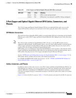
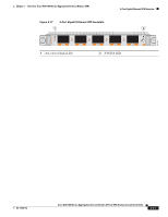
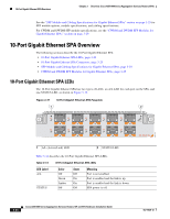
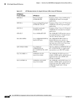
10-Port Gigabit Ethernet SPA Overview Chapter 3 Overview: Cisco ASR 1000 Series Aggregation Services Routers SPAs See the "SFP Module and Cabling Specifications for Gigabit Ethernet SPAs" section on page 3-25 for SFP module options, module specifications, and cabling specifications. For CWDM and DWDM SFP module specifications, see the "CWDM and DWDM SFP Modules for Gigabit Ethernet SPAs" section on page 3-29. 10-Port Gigabit Ethernet SPA Overview The following sections describe the 10-Port Gigabit Ethernet SPA: • 10-Port Gigabit Ethernet SPA LEDs, page 3-24 • 10-Port Gigabit Ethernet SPA Connectors, page 3-25 • SFP Module and Cabling Specifications for Gigabit Ethernet SPAs, page 3-25 • CWDM and DWDM SFP Modules for Gigabit Ethernet SPAs, page 3-29 10-Port Gigabit Ethernet SPA LEDs The 10-Port Gigabit Ethernet SPA has two types of LEDs: an A/L LED for each port on the SPA, and one STATUS LED, as shown in Figure 3-19. Figure 3-19 10-Port Gigabit Ethernet SPA Faceplate 1 2 1 A/L (Active/Link) LED 2 STATUS LED Table 3-14 describes the 10-Port Gigabit Ethernet SPA LEDs. Table 3-14 10-Port Gigabit Ethernet SPA LEDs LED Label A/L STATUS Color Off Green Amber Off State Off On On Off Meaning Port is not enabled. Port is enabled and the link is up. Port is enabled and the link is down. SPA power is off. 3-24 Cisco ASR 1000 Series Aggregation Services Routers SIP and SPA Hardware Installation Guide OL-14126-12
-
 1
1 -
2
-
3
-
4
-
5
-
6
-
7
-
8
-
9
-
10
-
11
-
12
-
13
-
14
-
15
-
16
-
17
-
18
-
19
-
20
-
21
-
22
-
23
-
24
-
25
-
26
-
27
-
28
-
29
-
30
-
31
-
32
-
33
-
34
-
35
-
36
-
37
-
38
-
39
-
40
-
41
-
42
-
43
-
44
-
45
-
46
-
47
-
48
-
49
-
50
-
51
-
52
-
53
-
54
-
55
-
56
-
57
-
58
-
59
-
60
-
 61
61 -
 62
62 -
 63
63 -
 64
64 -
 65
65 -
 66
66 -
 67
67 -
 68
68 -
 69
69 -
 70
70 -
 71
71 -
72
-
73
-
74
-
75
-
76
-
77
-
78
-
79
-
80
-
81
-
82
-
83
-
84
-
85
-
86
-
87
-
88
-
89
-
90
-
91
-
92
-
93
-
94
-
95
-
96
-
97
-
98
-
99
-
100
-
101
-
102
-
103
-
104
-
105
-
106
-
107
-
108
-
109
-
110
-
111
-
112
-
113
-
114
-
115
-
116
-
117
-
118
-
119
-
120
-
121
-
122
-
123
-
124
-
125
-
126
-
127
-
128
-
129
-
130
-
131
-
132
-
133
-
134
-
135
-
136
-
137
-
138
-
139
-
140
-
141
-
142
-
143
-
144
-
145
-
146
-
147
-
148
-
149
-
150
-
151
-
152
-
153
-
154
-
155
-
156
-
157
-
158
-
159
-
160
-
161
-
162
-
163
-
164
-
165
-
166
-
167
-
168
-
169
-
170
-
171
-
172
-
173
-
174
-
175
-
176
-
177
-
178
-
179
-
180
-
181
-
182
-
183
-
184
-
185
-
186
-
187
-
188
 |
 |