Cisco ASR1006 Hardware Installation Guide - Page 55
-Port and 8-Port Fast Ethernet SPA Cables, Connectors, and Pinouts, LED Label, Color, State, Meaning - power supply
 |
UPC - 882658196423
View all Cisco ASR1006 manuals
Add to My Manuals
Save this manual to your list of manuals |
Page 55 highlights
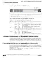
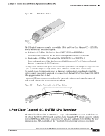
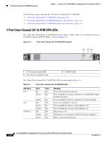
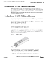
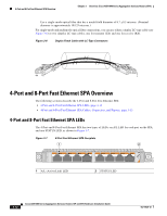
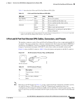
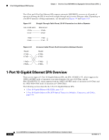
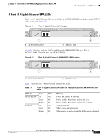
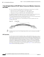
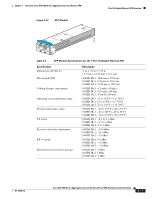
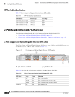
Chapter 3 Overview: Cisco ASR 1000 Series Aggregation Services Routers SPAs 4-Port and 8-Port Fast Ethernet SPA Overview Table 3-5 describes the 4-Port and 8-Port Fast Ethernet SPA LEDs. Table 3-5 4-Port and 8-Port Fast Ethernet SPA LEDs LED Label Color State Meaning Port Number Off A/L (0, 1, 2, 3, 4, 5, 6 or 7)1 Green Off Port is not enabled. On Port is enabled and the link is up. Amber On Port is enabled and the link is down. STATUS Off Off SPA power is off. Green On SPA is ready and operational. Amber On SPA power is on and good, and the SPA is being configured. 1. In this case, port number refers to the numbered LEDs on the 8-Port Fast Ethernet SPA (0, 1, 2, 3, 4, 5, 6, or 7). Each LED number on the 8-Port Fast Ethernet SPA references a port on the SPA. 4-Port and 8-Port Fast Ethernet SPA Cables, Connectors, and Pinouts The interface connectors on the 4-Port and 8-Port Fast Ethernet SPA are four or eight individual RJ-45 receptacles. You can use all interface connectors simultaneously. Each connection supports IEEE 802.3 and Ethernet 10/100BASE-T interfaces compliant with appropriate standards. Cisco does not supply Category 5 unshielded twisted pair (UTP) RJ-45 cables; these cables are available commercially. Figure 3-8 shows the RJ-45 connector. Table 3-6 lists the pinouts and signals for the RJ-45 connector. Figure 3-8 RJ-45 Connector Pinouts, Plug, and Receptacle 205060 8 7 6 5 4 3 2 1 RJ-45 connector Table 3-6 Pin 1 2 3 6 RJ-45 Connector Pinouts Description Transmit data + (TxD+) TxD- Receive data + (RxD+) RxD- Note Referring to the RJ-45 pinout in Table 3-6, proper common-mode line terminations should be used for the unused Category 5 UTP cable pairs 4/5 and 7/8. Common-mode termination reduces the contributions to electromagnetic interference (EMI) and susceptibility to common-mode sources. Wire pairs 4/5 and 7/8 are actively terminated in the RJ-45 port circuitry in the 4-Port and 8-Port Fast Ethernet SPA. OL-14126-12 Cisco ASR 1000 Series Aggregation Services Routers SIP and SPA Hardware Installation Guide 3-13
-
 1
1 -
2
-
3
-
4
-
5
-
6
-
7
-
8
-
9
-
10
-
11
-
12
-
13
-
14
-
15
-
16
-
17
-
18
-
19
-
20
-
21
-
22
-
23
-
24
-
25
-
26
-
27
-
28
-
29
-
30
-
31
-
32
-
33
-
34
-
35
-
36
-
37
-
38
-
39
-
40
-
41
-
42
-
43
-
44
-
45
-
46
-
47
-
48
-
49
-
 50
50 -
 51
51 -
 52
52 -
 53
53 -
 54
54 -
 55
55 -
 56
56 -
 57
57 -
 58
58 -
 59
59 -
 60
60 -
61
-
62
-
63
-
64
-
65
-
66
-
67
-
68
-
69
-
70
-
71
-
72
-
73
-
74
-
75
-
76
-
77
-
78
-
79
-
80
-
81
-
82
-
83
-
84
-
85
-
86
-
87
-
88
-
89
-
90
-
91
-
92
-
93
-
94
-
95
-
96
-
97
-
98
-
99
-
100
-
101
-
102
-
103
-
104
-
105
-
106
-
107
-
108
-
109
-
110
-
111
-
112
-
113
-
114
-
115
-
116
-
117
-
118
-
119
-
120
-
121
-
122
-
123
-
124
-
125
-
126
-
127
-
128
-
129
-
130
-
131
-
132
-
133
-
134
-
135
-
136
-
137
-
138
-
139
-
140
-
141
-
142
-
143
-
144
-
145
-
146
-
147
-
148
-
149
-
150
-
151
-
152
-
153
-
154
-
155
-
156
-
157
-
158
-
159
-
160
-
161
-
162
-
163
-
164
-
165
-
166
-
167
-
168
-
169
-
170
-
171
-
172
-
173
-
174
-
175
-
176
-
177
-
178
-
179
-
180
-
181
-
182
-
183
-
184
-
185
-
186
-
187
-
188
 |
 |