Dell PowerEdge C6100 Hardware Owner's Manual
Dell PowerEdge C6100 Manual
 |
View all Dell PowerEdge C6100 manuals
Add to My Manuals
Save this manual to your list of manuals |
Dell PowerEdge C6100 manual content summary:
- Dell PowerEdge C6100 | Hardware Owner's Manual - Page 1
Dell™ PowerEdge™ C6100 Systems Hardware Owner's Manual Regulatory Model XS23-TY3 - Dell PowerEdge C6100 | Hardware Owner's Manual - Page 2
loss of data if instructions are not followed. WARNING Dell Inc. is strictly forbidden. Trademarks used in this text: Dell, the DELL logo, and PowerEdge are trademarks of Dell Dell Inc. disclaims any proprietary interest in trademarks and trade names other than its own. Regulatory Model XS23-TY3 January - Dell PowerEdge C6100 | Hardware Owner's Manual - Page 3
During Startup 11 Front-Panel Features and Indicators 12 Hard-Drive Indicator Patterns 15 Back-Panel Features and Indicators 16 NIC Indicator Codes 18 Power and System Board Indicator Codes 20 Power Supply Indicator Codes 21 BMC Heart Beat LED 22 POST Error Codes 23 Collecting System - Dell PowerEdge C6100 | Hardware Owner's Manual - Page 4
Memory Configuration 40 IDE Configuration 41 Primary IDE Master 41 USB Configuration 43 PCI Configuration 44 Boot Menu 45 Boot Settings Configuration 45 Security Menu 45 Server Menu 47 System Management 48 Remote Access Configuration 48 IPMI Configuration 49 LAN Configuration 50 Power - Dell PowerEdge C6100 | Hardware Owner's Manual - Page 5
-Drive Blank 55 Installing a Hard-Drive Blank 55 Removing a Hard-Drive Carrier 56 Installing a Hard Drive Carrier 57 Removing a Hard Drive From a Hard-Drive Carrier 57 Installing a Hard Drive Into a Hard-Drive Carrier 58 Power Supplies 59 Removing a Power Supply 59 Installing a Power Supply - Dell PowerEdge C6100 | Hardware Owner's Manual - Page 6
77 Supported DIMM Configuration 77 Removing Memory Modules 79 Installing Memory Modules 80 Interposer Extenders 82 Removing the Interposer Extender 82 Installing the Interposer Extender 83 System Battery 84 Replacing the System Battery 84 RAID Battery (Optional 85 Removing the RAID Battery - Dell PowerEdge C6100 | Hardware Owner's Manual - Page 7
-For You and Your System 113 Installation Problems 113 Troubleshooting System Startup Failure 114 Troubleshooting External Connections 114 Troubleshooting the Video Subsystem 114 Troubleshooting a USB Device 114 Troubleshooting a Serial I/O Device 115 Troubleshooting a NIC 116 Contents 7 - Dell PowerEdge C6100 | Hardware Owner's Manual - Page 8
Battery 118 Troubleshooting Power Supplies 119 Troubleshooting System Cooling Problems 120 Troubleshooting a Fan 120 Troubleshooting System Memory 121 Troubleshooting a Hard Drive 123 Troubleshooting a Storage Controller 124 Troubleshooting Expansion Cards 125 Troubleshooting Processors 126 - Dell PowerEdge C6100 | Hardware Owner's Manual - Page 9
Power Distribution Board Connectors 139 Jumper Settings 139 System Configuration Jumper Settings 140 Backplane Jumper Settings 141 6 Getting Help 143 Contacting Dell 143 Glossary 145 Index 155 Contents 9 - Dell PowerEdge C6100 | Hardware Owner's Manual - Page 10
10 Contents - Dell PowerEdge C6100 | Hardware Owner's Manual - Page 11
Enters the BIOS Boot Manager. See "System Setup Options at Boot" on page 36. Starts Preboot eXecution Environment (PXE) boot. Enters the SAS Configuration Utility. For more information, see the SAS adapter documentation. Enters the RAID configuration utility. For - Dell PowerEdge C6100 | Hardware Owner's Manual - Page 12
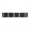
Front-Panel Features and Indicators Figure 1-1. Front Panel-3.5" Hard Drives With Four System Boards 1234 5 6 78 9 1-0 2-0 3-0 4-0 1-1 2-1 3-1 4-1 1-2 2-2 3-2 4-2 Figure 1-2. Front Panel-3.5" Hard Drives With Three System Boards 1234 5 6 78 9 1-0 1-1 1-2 1-3 2-0 2-1 2-2 2-3 - Dell PowerEdge C6100 | Hardware Owner's Manual - Page 13
Figure 1-4. Front Panel-2.5" Hard Drives With Four System Boards 1 234 5 *6 78 9 4-5 4-4 4-3 4-2 4-1 4-0 3-5 3-4 3-3 3-2 3-1 3-0 2-5 2-4 2-3 2-2 2-1 2-0 1-5 1-4 1-3 1-2 1-1 1-0 Figure 1-5. Front Panel-2.5" Hard Drives With Three System Boards 1 234 5 *6 7 8 9 4-7 4-6 - Dell PowerEdge C6100 | Hardware Owner's Manual - Page 14
2 minutes to display an image, depending on the amount of memory installed in the system. NOTE: On ACPI-compliant operating systems, turning off the system using the power button causes the system to perform a graceful shutdown before power to the system is turned off. NOTE: To force an ungraceful - Dell PowerEdge C6100 | Hardware Owner's Manual - Page 15
twelve hot-swappable 3.5-inch hard drives. Up to twenty four hot-swappable 2.5-inch hard drives. Applicable only for 2.5" hard drive system. Hard-Drive Indicator Patterns Figure 1-7. Hard Drive Indicators 1 1 hard-drive activity indicator (green) 2 2 hard-drive status indicator (green and amber - Dell PowerEdge C6100 | Hardware Owner's Manual - Page 16
8 9 10 Item Indicator, Button, Icon or Connector 1 Power supply 2 (PS2) 2 Power supply 1 (PS1) 3 USB connectors (2) 4 System identification indicator system board. Lights amber when the system needs attention due to a problem. Embedded 10/100/1000 NIC connectors. Embedded 10/100/1000 NIC - Dell PowerEdge C6100 | Hardware Owner's Manual - Page 17
2 minutes to display an image, depending on the amount of memory installed in the system. NOTE: On ACPI-compliant operating systems, turning off the system using the power button causes the system to perform a graceful shutdown before power to the system is turned off. NOTE: To force an ungraceful - Dell PowerEdge C6100 | Hardware Owner's Manual - Page 18
Figure 1-11. Enumeration-Two System Boards 4 2 NIC Indicator Codes Figure 1-12. NIC Indicators 1 2 1 link indicator NIC Status Indicator (link) Steady amber Blinks amber Steady green Blinks green Off 2 activity indicator Condition Link at 1 Gbps speed Identifying port with 1 Gbps connection - Dell PowerEdge C6100 | Hardware Owner's Manual - Page 19
NIC Status Indicator (activity) Steady green Blinks green Off Condition Link LAN / No access Accessing LAN Idle Figure 1-13. NIC Indicators (KVM Over IP Port) 1 2 1 link indicator NIC Status Indicator (link) Steady Green Off NIC Status Indicator (activity) Steady green Blinks green Green off 2 - Dell PowerEdge C6100 | Hardware Owner's Manual - Page 20
Blinks Blue Off Condition Power On S0/S1 BMC Critical condition event in Power Off mode S4/S5 BMC Critical condition event in Power On mode S0/S1 IPMI Via Chassis Identify Command On or ID Button Press ID On Only IPMI using Chassis Identify Command Blink On IPMI using Chassis Identify Command Off - Dell PowerEdge C6100 | Hardware Owner's Manual - Page 21
1-14. Power Supply Status Indicator 1 2 1 power supply 2 power supply indicator Power Supply Status Indicator Steady green Steady yellow Yellow off Condition Power supply is on (AC OK/DC OK) or in standby mode (90 VAC-264 VAC) Power supply faulty (UVP/OVP/OCP/SCP/OTP/Fan Fault) Power supply is - Dell PowerEdge C6100 | Hardware Owner's Manual - Page 22
BMC Heart Beat LED The system board provides BMC heart beat LED (CR24) for BMC debugs. When BMC firmware is ready, the BMC heart beat LED blinks. Figure 1-15. BMC Heart Beat LED 1 2 1 BMC heart beat LED 2 system board 22 About Your System - Dell PowerEdge C6100 | Hardware Owner's Manual - Page 23
of the BMC. Code Log in BMC Cause Corrective Actions 0000h Yes Timer Count Read/Write Error Remove AC power to the system for 10 seconds and restart the system. If the problem persists, see "Getting Help" on page 143. 0003h Yes CMOS Battery Error See "Troubleshooting the System Battery - Dell PowerEdge C6100 | Hardware Owner's Manual - Page 24
page 143. 0041h Yes Display Memory Error Remove AC power to the system for 10 seconds and restart the system. If the problem persists, see "Getting Help" on page 143. 0044h Yes DMAC Controller Error See "Troubleshooting System Memory" on page 121. If the problem persists, see "Getting Help - Dell PowerEdge C6100 | Hardware Owner's Manual - Page 25
Log in BMC Cause Corrective Actions 0047h Yes PMM Memory Allocation Error See "Troubleshooting System Memory" on page 121. If the problem persists, see "Getting Help" on page 143. 0048h Yes Password Check Error Reset password. See "Jumper Settings" on page 139. If the problem persists, see - Dell PowerEdge C6100 | Hardware Owner's Manual - Page 26
Yes ATAPI 4 Error 0085h Yes ATAPI 5 Error Corrective Actions See "Troubleshooting a Hard Drive" on page 123. See "Troubleshooting a Hard Drive" on page 123. Remove AC power to the system for 10 seconds and restart the system. If the problem persists, see "Getting Help" on page 143. Remove AC - Dell PowerEdge C6100 | Hardware Owner's Manual - Page 27
page 143. Remove AC power to the system for 10 seconds and restart the system. If the problem persists, see "Getting Help" on page 143. Ensure that the processor heat sinks are properly installed. See "Troubleshooting Processors" on page 126 and "Troubleshooting System Cooling Problems" on page 120 - Dell PowerEdge C6100 | Hardware Owner's Manual - Page 28
" on page 143. Remove AC power to the system for 10 seconds and restart the system. If the problem persists, see "Getting Help" on page 143. A BIOS update is required. If the problem persists, see "Getting Help" on page 143. A BIOS update is required. If the problem persists, see "Getting Help" on - Dell PowerEdge C6100 | Hardware Owner's Manual - Page 29
CPU 1 stepping no support 0181 Yes CPU 2 stepping no support 0182 Yes CPU 3 stepping no support 0183 Yes CPU 4 stepping no support Corrective Actions A BIOS update is required. If the problem persists, see "Getting Help" on page 143. A BIOS update is required. If the problem Started Guide. - Dell PowerEdge C6100 | Hardware Owner's Manual - Page 30
Model are different Corrective Actions Remove AC power to the system for 10 seconds and restart the system. If the problem persists, see "Getting Help" on page processor technical specifications outlined in your system's Getting Started Guide. Ensure that your processors match and conform to the - Dell PowerEdge C6100 | Hardware Owner's Manual - Page 31
To enable USB device, see "USB Configuration" on page 43. See "Troubleshooting a USB Device" on page 114. If the problem persists, see "Getting Help" on page 143. 8104h No USB OHCI EMUL Not Supported See "Troubleshooting a USB Device" on page 114. If the problem persists, see "Getting Help" on - Dell PowerEdge C6100 | Hardware Owner's Manual - Page 32
8400h Yes Redirect Memory Error See "Troubleshooting System Memory" on page 121. If the problem persists, see "Getting Help" on page 143. F001h No System Event Log Full Check the SEL for details on the events, then clear the SEL. F002h No BMC FRU Header checksum bad Remove AC power to the - Dell PowerEdge C6100 | Hardware Owner's Manual - Page 33
or as a separate document. The Getting Started Guide provides an overview of rack installation, system features, setting up your system, and technical specifications. NOTE: Always check for updates on support.dell.com/manuals and read the updates first because they often supersede information in - Dell PowerEdge C6100 | Hardware Owner's Manual - Page 34
34 About Your System - Dell PowerEdge C6100 | Hardware Owner's Manual - Page 35
, which is stored in Flash memory. The Flash memory supports the Plug and Play specification, and contains a System Setup program, the Power On Self Test (POST) routine, and the PCI auto-configuration utility. This system board supports system BIOS shadowing, enabling the BIOS to execute from 64-bit - Dell PowerEdge C6100 | Hardware Owner's Manual - Page 36
user to diagnose and fix problems on a system, which has not successfully booted the operating system. The centerpiece of the console redirection is the BIOS Console. The BIOS Console is a Flash ROM-resident utility that redirects input and output over a serial or modem connection. The BIOS supports - Dell PowerEdge C6100 | Hardware Owner's Manual - Page 37
Main Menu The main menu displays information about your system boards and BIOS. Main Screen Figure 2-1. Main System Setup Program Screen Use [ENTER],[TAB] or [SHIFT-TAB] to select a field Use [+] or [-] to configure system Time. Select Screen Select Item + - Change Field Tab Select Field F1 - Dell PowerEdge C6100 | Hardware Owner's Manual - Page 38
BIOS version. Check this version number when updating BIOS from the manufacturer. Displays the date the BIOS was created. Displays the BIOS the number of installed processors. System Memory Settings Option Size System Time System Date Description Displays how much memory (DRAM) is installed on the - Dell PowerEdge C6100 | Hardware Owner's Manual - Page 39
or prevents the system from booting, open BIOS and choose Load Optimal Defaults in the Exit menu to boot up normally. CPU Configuration Option Description Virtualization Technology (VT) (Disabled default) Enable this option when the processor supports VT. A full reset is needed to change - Dell PowerEdge C6100 | Hardware Owner's Manual - Page 40
Min. and Max. Use [+] or [-] to configure the value. CState: CPU idle is set to C2/C3/C4. C6 Support. When CPU is in idle mode. Memory Configuration Option Memory Frequency (Auto default) Memory Mode (Independent default) NUMA Support (Enabled default) Description Forces a DDR3 frequency slower - Dell PowerEdge C6100 | Hardware Owner's Manual - Page 41
/Slave is SATA Port 1/3 • AHCI/RAID • AHCI Port 0~5 Enables or disables device write protection. This is effective only if the device is accessed through BIOS. Selects the time out value for detecting ATA/ATAPI device(s). Primary IDE Master To configure Primary, Secondary, Third or Fourth device - Dell PowerEdge C6100 | Hardware Owner's Manual - Page 42
supported. S.M.A.R.T. Indicates whether S.M.A.R.T. mode is supported. Type (Auto default) Selects which type of device is installed or select Auto to enable the system to automatically configure determines the data transfer mode used by IDE drives. PIO mode uses the processor's registers for - Dell PowerEdge C6100 | Hardware Owner's Manual - Page 43
Memory Technology) reports drive degradation to the Configuration is shown in SETUP screen when USB Mass Storage is plugged. If USB device (Floppy, CDROM) is used to install RedHat® Linux 9.0, change USB 2.0 Controller Mode to FullSpeed to work around it, because RedHat Linux 9.0 is not supported - Dell PowerEdge C6100 | Hardware Owner's Manual - Page 44
as hard disk. Forced FDD option can be used to force a formatted hard drive to boot as FDD (e.g. ZIP drive) PCI Configuration Option Description NIC Function Support (PXE NIC Function Disable or PXE/iSCSI Support default) NIC1 Option ROM (Enable Set OnBoard 82576EB Disable/Enable Option ROM - Dell PowerEdge C6100 | Hardware Owner's Manual - Page 45
drives. Boot Settings Configuration Option Quick Boot (Enabled default) Quiet Boot (Disabled default) Wait For 'F1' If Error (Disabled default) Description Allows BIOS User Password Description Displays whether the supervisor password is installed or not. Displays whether the user password - Dell PowerEdge C6100 | Hardware Owner's Manual - Page 46
Setup Utility but the fields cannot be changed. • Limited: allows only limited fields to be changed such as date and time. • Full Access: allows user access to the Setup Utility and the fields can be changed. Installs, changes or clears the password. Selects the password check mode: Setup: checks - Dell PowerEdge C6100 | Hardware Owner's Manual - Page 47
is set to User define. The selection of Restore on AC Power Loss setup to Power-on or Last State takes 60 seconds for running BMC initialization after AC Power on. Option Description Power Management (Node Sets power mode. The options are: Management default) • Maximum Performance • Operating - Dell PowerEdge C6100 | Hardware Owner's Manual - Page 48
number. Displays system serial number. Displays chassis part number. Displays chassis serial numbers. Displays current BIOS version. Displays BMC device ID. Displays BMC firmware version. Displays FCB firmware version. Remote Access Configuration Option Description Remote Access (Enabled default - Dell PowerEdge C6100 | Hardware Owner's Manual - Page 49
PXE Option ROM Configuration. Therefore, we suggest users change to in PXE OPROM Configuration in order to avoid that the Hyper Terminal on remote side is discontinued when pressing . IPMI Configuration Option Status Of BMC BMC Firmware Revision View BMC System Event - Dell PowerEdge C6100 | Hardware Owner's Manual - Page 50
Config Command. Proper value is below 16. Sets BMC IP address source from BIOS. Power Throttling Configuration Option Power Throttling Power CAP Chassis CAP Description Enable or disable Power throttling Enable or disable Power CAP Set Chassis CAP value NOTE: The default values are dependant on - Dell PowerEdge C6100 | Hardware Owner's Manual - Page 51
status is static, Subnet Mask is useful. Default Gateway IP Option Default Gateway IP (default value depends on BMC setting) Exit Menu Description Enters default Gateway IP in decimal in the form of XXX.XXX.XXX.XXX (XXX is less than 256 and in - Dell PowerEdge C6100 | Hardware Owner's Manual - Page 52
settings. The optimal settings default values are quite demanding and your system might not function properly if you are using slower memory chips or other kinds of low-performance components. If you select this item and press Enter, a dialog box asks if you want to install fail-safe settings for - Dell PowerEdge C6100 | Hardware Owner's Manual - Page 53
should only perform troubleshooting and simple repairs as authorized in your product documentation, or as directed by the online or telephone service and support team. Damage due to servicing that is not authorized by Dell is not covered by your warranty. Read and follow the safety instructions that - Dell PowerEdge C6100 | Hardware Owner's Manual - Page 54
should only perform troubleshooting and simple repairs as authorized in your product documentation, or as directed by the online or telephone service and support team. Damage due to servicing that is not authorized by Dell is not covered by your warranty. Read and follow the safety instructions that - Dell PowerEdge C6100 | Hardware Owner's Manual - Page 55
the blank out until it is free of the drive bay. See Figure 3-2. Figure 3-2. Removing or Installing a Hard-Drive Blank 1 1 hard-drive blank Installing a Hard-Drive Blank Align the hard-drive blank with the drive bay and insert the blank into the drive bay until the retention latch clicks into place - Dell PowerEdge C6100 | Hardware Owner's Manual - Page 56
should only perform troubleshooting and simple repairs as authorized in your product documentation, or as directed by the online or telephone service and support team. Damage due to servicing that is not authorized by Dell is not covered by your warranty. Read and follow the safety instructions that - Dell PowerEdge C6100 | Hardware Owner's Manual - Page 57
should only perform troubleshooting and simple repairs as authorized in your product documentation, or as directed by the online or telephone service and support team. Damage due to servicing that is not authorized by Dell is not covered by your warranty. Read and follow the safety instructions that - Dell PowerEdge C6100 | Hardware Owner's Manual - Page 58
should only perform troubleshooting and simple repairs as authorized in your product documentation, or as directed by the online or telephone service and support team. Damage due to servicing that is not authorized by Dell is not covered by your warranty. Read and follow the safety instructions that - Dell PowerEdge C6100 | Hardware Owner's Manual - Page 59
two hard drives, and six memory modules * Full configuration denotes support for the maximum number of processors, hard drives, and memory modules. Removing a Power Supply CAUTION: Many repairs may only be done by a certified service technician. You should only perform troubleshooting and simple - Dell PowerEdge C6100 | Hardware Owner's Manual - Page 60
should only perform troubleshooting and simple repairs as authorized in your product documentation, or as directed by the online or telephone service and support team. Damage due to servicing that is not authorized by Dell is not covered by your warranty. Read and follow the safety instructions that - Dell PowerEdge C6100 | Hardware Owner's Manual - Page 61
should only perform troubleshooting and simple repairs as authorized in your product documentation, or as directed by the online or telephone service and support team. Damage due to servicing that is not authorized by Dell is not covered by your warranty. Read and follow the safety instructions that - Dell PowerEdge C6100 | Hardware Owner's Manual - Page 62
should only perform troubleshooting and simple repairs as authorized in your product documentation, or as directed by the online or telephone service and support team. Damage due to servicing that is not authorized by Dell is not covered by your warranty. Read and follow the safety instructions that - Dell PowerEdge C6100 | Hardware Owner's Manual - Page 63
should only perform troubleshooting and simple repairs as authorized in your product documentation, or as directed by the online or telephone service and support team. Damage due to servicing that is not authorized by Dell is not covered by your warranty. Read and follow the safety instructions that - Dell PowerEdge C6100 | Hardware Owner's Manual - Page 64
perform troubleshooting and simple repairs as authorized in your product documentation, or as directed by the online or telephone service and support team. Damage due to servicing that is not authorized by Dell is not covered by your warranty. Read and follow the safety instructions been powered down - Dell PowerEdge C6100 | Hardware Owner's Manual - Page 65
4 Using a Phillips screwdriver, loosen one of the heat-sink retention screws. See Figure 3-8. Wait for 30 seconds for the heat sink to loosen from the processor. 5 Remove the other three heat-sink retention screws. 6 Gently lift the heat sink off the processor and set the heat sink aside with - Dell PowerEdge C6100 | Hardware Owner's Manual - Page 66
should only perform troubleshooting and simple repairs as authorized in your product documentation, or as directed by the online or telephone service and support team. Damage due to servicing that is not authorized by Dell is not covered by your warranty. Read and follow the safety instructions that - Dell PowerEdge C6100 | Hardware Owner's Manual - Page 67
4 Remove the heat sink, see "Removing the Heat Sink" on page 64. CAUTION: The processor is held in its socket under strong pressure. Be aware that the release lever can spring up suddenly if not firmly grasped. 5 Position your thumb firmly over the processor socket-release lever and release the - Dell PowerEdge C6100 | Hardware Owner's Manual - Page 68
should only perform troubleshooting and simple repairs as authorized in your product documentation, or as directed by the online or telephone service and support team. Damage due to servicing that is not authorized by Dell is not covered by your warranty. Read and follow the safety instructions that - Dell PowerEdge C6100 | Hardware Owner's Manual - Page 69
should only perform troubleshooting and simple repairs as authorized in your product documentation, or as directed by the online or telephone service and support team. Damage due to servicing that is not authorized by Dell is not covered by your warranty. Read and follow the safety instructions that - Dell PowerEdge C6100 | Hardware Owner's Manual - Page 70
Figure 3-10. Removing the Expansion-Card Assembly 1 2 1 screw (5) 2 expansion-card assembly 6 Remove the screw securing the expansion card. Figure 3-11. Removing the Expansion Card 1 4 1 expansion-card slot cover 3 expansion card 2 3 2 screw 4 expansion-card connector 70 Installing System - Dell PowerEdge C6100 | Hardware Owner's Manual - Page 71
should only perform troubleshooting and simple repairs as authorized in your product documentation, or as directed by the online or telephone service and support team. Damage due to servicing that is not authorized by Dell is not covered by your warranty. Read and follow the safety instructions that - Dell PowerEdge C6100 | Hardware Owner's Manual - Page 72
should only perform troubleshooting and simple repairs as authorized in your product documentation, or as directed by the online or telephone service and support team. Damage due to servicing that is not authorized by Dell is not covered by your warranty. Read and follow the safety instructions that - Dell PowerEdge C6100 | Hardware Owner's Manual - Page 73
3 Remove the expansion card. See "Removing the Expansion Card" on page 69. 4 Remove the two screws securing the expansion-card connector to the expansion-card bracket. See Figure 3-12. 5 Pull the expansion-card connector away from the expansion-card bracket. See Figure 3-12. Figure 3-12. Removing - Dell PowerEdge C6100 | Hardware Owner's Manual - Page 74
should only perform troubleshooting and simple repairs as authorized in your product documentation, or as directed by the online or telephone service and support team. Damage due to servicing that is not authorized by Dell is not covered by your warranty. Read and follow the safety instructions that - Dell PowerEdge C6100 | Hardware Owner's Manual - Page 75
should only perform troubleshooting and simple repairs as authorized in your product documentation, or as directed by the online or telephone service and support team. Damage due to servicing that is not authorized by Dell is not covered by your warranty. Read and follow the safety instructions that - Dell PowerEdge C6100 | Hardware Owner's Manual - Page 76
should only perform troubleshooting and simple repairs as authorized in your product documentation, or as directed by the online or telephone service and support team. Damage due to servicing that is not authorized by Dell is not covered by your warranty. Read and follow the safety instructions that - Dell PowerEdge C6100 | Hardware Owner's Manual - Page 77
should only perform troubleshooting and simple repairs as authorized in your product documentation, or as directed by the online or telephone service and support team. Damage due to servicing that is not authorized by Dell is not covered by your warranty. Read and follow the safety instructions that - Dell PowerEdge C6100 | Hardware Owner's Manual - Page 78
9 DIMM1_CHB 11 DIMM1_CHC 12 11 10 9 8 7 2 DIMM1_CHC 4 DIMM1_CHB 6 DIMM1_CHA 8 DIMM0_CHA 10 DIMM0_CHB 12 DIMM0_CHC Table 3-2. Memory Module Configurations DIMM DIMM0 DIMM1 DIMM0 DIMM1 DIMM0 DIMM1 Processor 0 CH A CH B CH C 1 - - - - - 4 - - - - 78 Installing System Components - Dell PowerEdge C6100 | Hardware Owner's Manual - Page 79
should only perform troubleshooting and simple repairs as authorized in your product documentation, or as directed by the online or telephone service and support team. Damage due to servicing that is not authorized by Dell is not covered by your warranty. Read and follow the safety instructions that - Dell PowerEdge C6100 | Hardware Owner's Manual - Page 80
should only perform troubleshooting and simple repairs as authorized in your product documentation, or as directed by the online or telephone service and support team. Damage due to servicing that is not authorized by Dell is not covered by your warranty. Read and follow the safety instructions that - Dell PowerEdge C6100 | Hardware Owner's Manual - Page 81
module socket align with the ejectors on the other sockets that have memory modules installed. 9 Repeat step 5 through step 8 of this procedure to install the remaining memory modules in the approved configurations. See Table 3-2. 10 Replace the cooling shroud. See "Installing the Cooling Shroud - Dell PowerEdge C6100 | Hardware Owner's Manual - Page 82
should only perform troubleshooting and simple repairs as authorized in your product documentation, or as directed by the online or telephone service and support team. Damage due to servicing that is not authorized by Dell is not covered by your warranty. Read and follow the safety instructions that - Dell PowerEdge C6100 | Hardware Owner's Manual - Page 83
should only perform troubleshooting and simple repairs as authorized in your product documentation, or as directed by the online or telephone service and support team. Damage due to servicing that is not authorized by Dell is not covered by your warranty. Read and follow the safety instructions that - Dell PowerEdge C6100 | Hardware Owner's Manual - Page 84
should only perform troubleshooting and simple repairs as authorized in your product documentation, or as directed by the online or telephone service and support team. Damage due to servicing that is not authorized by Dell is not covered by your warranty. Read and follow the safety instructions that - Dell PowerEdge C6100 | Hardware Owner's Manual - Page 85
should only perform troubleshooting and simple repairs as authorized in your product documentation, or as directed by the online or telephone service and support team. Damage due to servicing that is not authorized by Dell is not covered by your warranty. Read and follow the safety instructions that - Dell PowerEdge C6100 | Hardware Owner's Manual - Page 86
3-19. Figure 3-19. Removing and Installing the RAID Battery 4 3 2 1 1 RAID battery latch 3 RAID battery carrier 2 RAID battery 4 system-board assembly Installing the RAID Battery 1 Insert the RAID battery into the battery carrier until the RAID battery latch locks into place. See Figure 3-19 - Dell PowerEdge C6100 | Hardware Owner's Manual - Page 87
should only perform troubleshooting and simple repairs as authorized in your product documentation, or as directed by the online or telephone service and support team. Damage due to servicing that is not authorized by Dell is not covered by your warranty. Read and follow the safety instructions that - Dell PowerEdge C6100 | Hardware Owner's Manual - Page 88
the interposer extender. See Figure 3-20. 2 Replace the screws securing the RAID battery carrier to the interposer extender. See Figure 3-20. 3 Install the RAID battery into the RAID battery carrier. See "Installing the RAID Battery" on page 86. 4 Replace the system-board assembly. See "Installing - Dell PowerEdge C6100 | Hardware Owner's Manual - Page 89
perform troubleshooting and simple repairs as authorized in your product documentation, or as directed by the online or telephone service and support team. Damage due to servicing that is not authorized by Dell is not covered by your warranty. Read and follow the safety instructions drive and power - Dell PowerEdge C6100 | Hardware Owner's Manual - Page 90
system-board assembly. 4 Transfer the processors to the new system board. See "Removing a Processor" on page 66 and "Installing a Processor" on page 68. 5 Remove the memory modules and transfer them to the same locations on the new board. See "Interposer Extenders" on page 82 and "Installing - Dell PowerEdge C6100 | Hardware Owner's Manual - Page 91
drive and power perform troubleshooting and simple repairs as authorized in your product documentation, or as directed by the online or telephone service and support team. Damage due to servicing that is not authorized by Dell is not covered by your warranty. Read and follow the safety instructions - Dell PowerEdge C6100 | Hardware Owner's Manual - Page 92
4 securing screw Closing the System 1 Place the cover on the chassis and slide it to the front of the chassis until it snaps into place. See Figure 3-22. 2 Secure the for some time after the system has been powered down. Allow time for the fan to stop spinning before removing it from the - Dell PowerEdge C6100 | Hardware Owner's Manual - Page 93
should only perform troubleshooting and simple repairs as authorized in your product documentation, or as directed by the online or telephone service and support team. Damage due to servicing that is not authorized by Dell is not covered by your warranty. Read and follow the safety instructions that - Dell PowerEdge C6100 | Hardware Owner's Manual - Page 94
should only perform troubleshooting and simple repairs as authorized in your product documentation, or as directed by the online or telephone service and support team. Damage due to servicing that is not authorized by Dell is not covered by your warranty. Read and follow the safety instructions that - Dell PowerEdge C6100 | Hardware Owner's Manual - Page 95
routing of the cable underneath the tabs on the chassis as you remove them from the system. You must route these cables properly when you replace them to prevent the cables from being pinched or crimped. 5 Remove the screws securing the first power distribution board to the system. See Figure 3-24 - Dell PowerEdge C6100 | Hardware Owner's Manual - Page 96
should only perform troubleshooting and simple repairs as authorized in your product documentation, or as directed by the online or telephone service and support team. Damage due to servicing that is not authorized by Dell is not covered by your warranty. Read and follow the safety instructions that - Dell PowerEdge C6100 | Hardware Owner's Manual - Page 97
should only perform troubleshooting and simple repairs as authorized in your product documentation, or as directed by the online or telephone service and support team. Damage due to servicing that is not authorized by Dell is not covered by your warranty. Read and follow the safety instructions that - Dell PowerEdge C6100 | Hardware Owner's Manual - Page 98
should only perform troubleshooting and simple repairs as authorized in your product documentation, or as directed by the online or telephone service and support team. Damage due to servicing that is not authorized by Dell is not covered by your warranty. Read and follow the safety instructions that - Dell PowerEdge C6100 | Hardware Owner's Manual - Page 99
should only perform troubleshooting and simple repairs as authorized in your product documentation, or as directed by the online or telephone service and support team. Damage due to servicing that is not authorized by Dell is not covered by your warranty. Read and follow the safety instructions that - Dell PowerEdge C6100 | Hardware Owner's Manual - Page 100
holder. Figure 3-27. 8 Disconnect all the cables from the upper midplane. See Figure 5-9. Note the routing of the cable underneath the tabs on the chassis as you remove them from the system. You must route these cables properly when you replace them to prevent the cables from being pinched or - Dell PowerEdge C6100 | Hardware Owner's Manual - Page 101
Figure 3-27. Removing and Installing the Upper Midplane 1 2 1 screw (9) 2 upper midplane 10 Remove the screws that secure the mid-plane holder support to the chassis. See Figure 3-28. 11 Lift the mid-plane holder support out of the chassis. Figure 3-28. Installing System Components 101 - Dell PowerEdge C6100 | Hardware Owner's Manual - Page 102
Figure 3-28. Removing and Installing the Mid-Plane Holder Support 1 2 1 screw (4) 2 mid-plane holder support 12 Remove the screws that secure the mid-plane holder to the chassis. Figure 3-29. 13 Lift the mid-plane holder out of the chassis. See Figure 3-29. 102 Installing System Components - Dell PowerEdge C6100 | Hardware Owner's Manual - Page 103
mid-plane holder 14 Remove the screws that secure the lower midplane to the chassis. Figure 3-30. 15 Disconnect all the cables from the lower midplane. See Figure 5-9. Note the routing of the cable underneath the tabs on the chassis as you remove them from the system. You must route these cables - Dell PowerEdge C6100 | Hardware Owner's Manual - Page 104
should only perform troubleshooting and simple repairs as authorized in your product documentation, or as directed by the online or telephone service and support team. Damage due to servicing that is not authorized by Dell is not covered by your warranty. Read and follow the safety instructions that - Dell PowerEdge C6100 | Hardware Owner's Manual - Page 105
should only perform troubleshooting and simple repairs as authorized in your product documentation, or as directed by the online or telephone service and support team. Damage due to servicing that is not authorized by Dell is not covered by your warranty. Read and follow the safety instructions that - Dell PowerEdge C6100 | Hardware Owner's Manual - Page 106
See Figure 3-32. 6 Disconnect all the cables from the backplane. See Figure 5-3 for 3.5-inch hard drives and Figure 5-6 for 2.5-inch hard drives. Note the routing of the cable underneath the tabs on the chassis as you remove them from the system. You must route these cables properly when you replace - Dell PowerEdge C6100 | Hardware Owner's Manual - Page 107
replace them to prevent the cables from being pinched or crimped. 8 Remove the hard-drive cage from the chassis. See Figure 3-32. Figure 3-32. Removing and Installing the Hard-Drive Cage 1 2 1 hard-drive cage 2 front-panel assembly (2) 9 Remove the screws that secure the backplane to the hard - Dell PowerEdge C6100 | Hardware Owner's Manual - Page 108
should only perform troubleshooting and simple repairs as authorized in your product documentation, or as directed by the online or telephone service and support team. Damage due to servicing that is not authorized by Dell is not covered by your warranty. Read and follow the safety instructions that - Dell PowerEdge C6100 | Hardware Owner's Manual - Page 109
should only perform troubleshooting and simple repairs as authorized in your product documentation, or as directed by the online or telephone service and support team. Damage due to servicing that is not authorized by Dell is not covered by your warranty. Read and follow the safety instructions that - Dell PowerEdge C6100 | Hardware Owner's Manual - Page 110
. 7 Remove the screws that secure the front-panel assemblies to the chassis. See Figure 3-32. 8 Remove the hard-drive cage from the chassis. See Figure 3-32. 9 Remove the screws that secure the front-panel assembly to the hard-drive cage. See Figure 3-34. 10 Remove the front-panel assembly from the - Dell PowerEdge C6100 | Hardware Owner's Manual - Page 111
should only perform troubleshooting and simple repairs as authorized in your product documentation, or as directed by the online or telephone service and support team. Damage due to servicing that is not authorized by Dell is not covered by your warranty. Read and follow the safety instructions that - Dell PowerEdge C6100 | Hardware Owner's Manual - Page 112
or crimped. 8 Connect all the cables to the backplane. See Figure 5-3 for 3.5-inch hard drives and Figure 5-6 for 2.5-inch hard drives. You must route these cables properly through the tabs on the chassis to prevent them from being pinched or crimped. 9 Close the system. See "Closing the System - Dell PowerEdge C6100 | Hardware Owner's Manual - Page 113
support team. Damage due to servicing that is not authorized by Dell is not covered by your warranty. Read and follow the safety instructions that came with the product. Installation Problems Perform the following checks if you are troubleshooting an installation problem: • Check all cable and power - Dell PowerEdge C6100 | Hardware Owner's Manual - Page 114
Troubleshooting System Startup Failure If your system halts during startup, especially after installing an operating system or reconfiguring your system's hardware, check for invalid memory configurations. These could cause the system to halt at startup without any video output. See "System Memory" - Dell PowerEdge C6100 | Hardware Owner's Manual - Page 115
system and restoring the BIOS to the default settings. 7 Reconnect and power on each USB device one at a time. 8 If a device causes the same problem, power down the device, replace the USB cable, and power up the device. If the problem persists, replace the device. If all troubleshooting fails, see - Dell PowerEdge C6100 | Hardware Owner's Manual - Page 116
instead of an integrated NIC, see the documentation for the NIC card. 3 Ensure that the appropriate drivers are installed and the protocols are bound. See the NIC's documentation. 4 Enter the System Setup exceed the maximum length. If all troubleshooting fails, see "Getting Help" on page 143. 116 - Dell PowerEdge C6100 | Hardware Owner's Manual - Page 117
should only perform troubleshooting and simple repairs as authorized in your product documentation, or as directed by the online or telephone service and support team. Damage due to servicing that is not authorized by Dell is not covered by your warranty. Read and follow the safety instructions that - Dell PowerEdge C6100 | Hardware Owner's Manual - Page 118
should only perform troubleshooting and simple repairs as authorized in your product documentation, or as directed by the online or telephone service and support team. Damage due to servicing that is not authorized by Dell is not covered by your warranty. Read and follow the safety instructions that - Dell PowerEdge C6100 | Hardware Owner's Manual - Page 119
should only perform troubleshooting and simple repairs as authorized in your product documentation, or as directed by the online or telephone service and support team. Damage due to servicing that is not authorized by Dell is not covered by your warranty. Read and follow the safety instructions that - Dell PowerEdge C6100 | Hardware Owner's Manual - Page 120
should only perform troubleshooting and simple repairs as authorized in your product documentation, or as directed by the online or telephone service and support team. Damage due to servicing that is not authorized by Dell is not covered by your warranty. Read and follow the safety instructions that - Dell PowerEdge C6100 | Hardware Owner's Manual - Page 121
should only perform troubleshooting and simple repairs as authorized in your product documentation, or as directed by the online or telephone service and support team. Damage due to servicing that is not authorized by Dell is not covered by your warranty. Read and follow the safety instructions that - Dell PowerEdge C6100 | Hardware Owner's Manual - Page 122
the diagnostic indicators on the front of the system. 20 If the memory problem is still indicated, repeat step 13 through step 19 for each memory module installed. If the problem persists after all memory modules have been checked, see "Getting Help" on page 143. 122 Troubleshooting Your System - Dell PowerEdge C6100 | Hardware Owner's Manual - Page 123
the safety instructions that came with the product. CAUTION: This troubleshooting procedure can destroy data stored on the hard drive. Before you proceed, back up all files on the hard drive. 1 If your system has a RAID controller and your hard drives are configured in a RAID array, perform the - Dell PowerEdge C6100 | Hardware Owner's Manual - Page 124
should only perform troubleshooting and simple repairs as authorized in your product documentation, or as directed by the online or telephone service and support team. Damage due to servicing that is not authorized by Dell is not covered by your warranty. Read and follow the safety instructions that - Dell PowerEdge C6100 | Hardware Owner's Manual - Page 125
should only perform troubleshooting and simple repairs as authorized in your product documentation, or as directed by the online or telephone service and support team. Damage due to servicing that is not authorized by Dell is not covered by your warranty. Read and follow the safety instructions that - Dell PowerEdge C6100 | Hardware Owner's Manual - Page 126
perform troubleshooting and simple repairs as authorized in your product documentation, or as directed by the online or telephone service and support team. Damage due to servicing that is not authorized by Dell is not covered by your warranty. Read and follow the safety instructions the problem - Dell PowerEdge C6100 | Hardware Owner's Manual - Page 127
on page 68. 14 Repeat step 9 through step 11. If you have tested both the processors and the problem persists, the system board is faulty. See "Getting Help" on page 143. IRQ Assignment Conflicts Most PCI Processor Primary IDE controller Secondary IDE controller Troubleshooting Your System 127 - Dell PowerEdge C6100 | Hardware Owner's Manual - Page 128
128 Troubleshooting Your System - Dell PowerEdge C6100 | Hardware Owner's Manual - Page 129
-E mezzanine card connector 3 DIMM sockets for processor 1 5 main power connector 7 system battery 9 DIMM sockets for processor 0 11 onboard SATA2 connector 2 13 SGPIO connector 15 onboard SATA2 connector 5 2 system configuration jumper 4 processor 0 6 processor 1 8 front panel connector 10 onboard - Dell PowerEdge C6100 | Hardware Owner's Manual - Page 130
17 expansion slot 19 power button 21 serial port 23 NIC2 connector (RJ45) 25 ID LED 18 BMC debug connector 20 VGA port 22 KVM over IP port 24 NIC1 connector (RJ45) 26 USB port Backplane Connectors 3.5" drives Figure 5-2. Front View of the Backplane 1 2 3 4 5 1 3.5" backplane 2 SATA2 and - Dell PowerEdge C6100 | Hardware Owner's Manual - Page 131
3 for system board 2 (from top to bottom) bottom) 11 SATA2 hard drive connectors 1, 2, 12 SATA2 hard drive connectors 1, 2, and 3 for system board 3 (from top to and 3 for system board 4 (from top to bottom) bottom) 13 backplane power connector for power supply 2 Jumpers and Connectors 131 - Dell PowerEdge C6100 | Hardware Owner's Manual - Page 132
2.5" drives Figure 5-4. Front View of the Backplane 1 2 5 4 3 1 SATA2 and SAS connectors 1 to 6 for 2 SATA2 and SAS connectors 1 to 6 for system board 1 (from left to right) system - Dell PowerEdge C6100 | Hardware Owner's Manual - Page 133
1 system fan board connector 2 backplane power connector for power supply 1 3 SATA2 hard drive connectors 1 to 6 4 SATA2 hard drive connectors 1 to 6 for for system board 4 (from right to left) system board 2 (from right to left) 5 backplane jumper 6 SGPIO connector A for system board 1 7 - Dell PowerEdge C6100 | Hardware Owner's Manual - Page 134
7 mini-SAS connector for system boards 3 and 4 (hard drive 1, 2, 3, and 4) 9 mini-SAS connector for system boards 1 and 2 (hard drive 1, 2, 3, and 4) 11 midplane Figure 5-8. Midplane Connectors-2.5" 2 midplane connector 2 4 midplane power connector for system boards 3 and 4 6 front panel connector - Dell PowerEdge C6100 | Hardware Owner's Manual - Page 135
9 10 11 12 1 USB connector 3 onboard SATA2 connector 1 5 onboard SATA2 connector 3 7 onboard SATA2 connector 5 9 SGPIO connector A 11 2x4-pin power connector 2 front panel connector 4 onboard SATA2 connector 2 6 onboard SATA2 connector 4 8 onboard SATA2 connector 6 10 SGPIO connector B 12 2x5-pin - Dell PowerEdge C6100 | Hardware Owner's Manual - Page 136
Mezzanine Card Connectors Figure 5-10. Mezzanine Card Connectors-SAS 1 2 3 1 mini-SAS connector 3 mezzanine card 5 SAS port 5 7 SGPIO connector B 7 654 2 daughter card connector 4 SAS port 4 6 SGPIO connector A 136 Jumpers and Connectors - Dell PowerEdge C6100 | Hardware Owner's Manual - Page 137
Figure 5-11. Mezzanine Card Connectors-Infiniband 1 23 1 QSFP cage 1 3 bridge card connector 2 QSFP cage 2 Jumpers and Connectors 137 - Dell PowerEdge C6100 | Hardware Owner's Manual - Page 138
use the jumper for P12V to power on 7 system fan control connector 8 system fan board power connector 2 9 PIC firmware update connector 10 system fan board connector 2 11 system fan board connector 1 12 system fan connectors 3 13 hard drive backplane I2C connector 14 system fan connectors - Dell PowerEdge C6100 | Hardware Owner's Manual - Page 139
should only perform troubleshooting and simple repairs as authorized in your product documentation, or as directed by the online or telephone service and support team. Damage due to servicing that is not authorized by Dell is not covered by your warranty. Read and follow the safety instructions that - Dell PowerEdge C6100 | Hardware Owner's Manual - Page 140
Off ME Function *Disable Disable for Debugs Reserved for BIOS PCI-E Setup BIOS Clear Password *Disable BIOS Clear CMOS *Disable System Reset *Disable On Enable - Enable Enable Enable NOTE: The * in the table of system configuration jumper describes the default status and the default state - Dell PowerEdge C6100 | Hardware Owner's Manual - Page 141
perform troubleshooting and simple repairs as authorized in your product documentation, or as directed by the online or telephone service and support team. Damage due to servicing that is not authorized by Dell is not covered by your warranty. Read and follow the safety instructions hard drive Type - Dell PowerEdge C6100 | Hardware Owner's Manual - Page 142
142 Jumpers and Connectors - Dell PowerEdge C6100 | Hardware Owner's Manual - Page 143
, or Dell product catalog. Dell provides several online and telephone-based support and service options. Availability varies by country and product, and some services may not be available in your area. To contact Dell for sales, technical support, or customer service issues: 1 Visit support.dell.com - Dell PowerEdge C6100 | Hardware Owner's Manual - Page 144
144 Getting Help - Dell PowerEdge C6100 | Hardware Owner's Manual - Page 145
memory, and a hard drive. The modules are mounted into a chassis that includes power supplies and fans. BMC - Baseboard management controller. bootable media - A CD, diskette, or USB memory fast storage area that keeps a copy of data or instructions for quick data retrieval. cm - Centimeter(s). COMn - Dell PowerEdge C6100 | Hardware Owner's Manual - Page 146
DRAM chips. driver - See device driver. DVD - Digital versatile disc or digital video disc. ECC - Error checking and correction. EMI - Electromagnetic interference. ERA - Embedded remote access. ERA allows you to perform remote, or out-of-band, server management on your network server using a remote - Dell PowerEdge C6100 | Hardware Owner's Manual - Page 147
physical interface between the processor and the main memory (RAM). FTP - File transfer protocol. g hard drive or an internal cooling fan, into the host system while the system is powered on drive electronics. A standard interface between the system board and storage devices. iDRAC - Internet Dell - Dell PowerEdge C6100 | Hardware Owner's Manual - Page 148
plugs containing a wire fit down over the pins. The wire connects the pins and creates a circuit, providing a simple and reversible method of changing the circuitry in a board ,576 bytes. However, when referring to hard-drive capacity, the term is often rounded to mean 1,000,000 bytes. 148 Glossary - Dell PowerEdge C6100 | Hardware Owner's Manual - Page 149
memory. Memory that does not lose its contents when you turn off your system. NVRAM is used for maintaining the date, time, and system configuration information. parity - Redundant information that is associated with a block of data. parity stripe - In RAID arrays, a striped hard drive containing - Dell PowerEdge C6100 | Hardware Owner's Manual - Page 150
multiple power outlets that provides electrical power to servers and storage systems in a rack. peripheral - An internal or external device, such as a diskette drive or keyboard, connected to a system. pixel - A single point on a video display. Pixels are arranged in rows and columns to create an - Dell PowerEdge C6100 | Hardware Owner's Manual - Page 151
connect a modem to the system. service tag - A bar code label on the system used to identify it when you call Dell for technical support. SMART - Self-Monitoring Analysis and Reporting Technology. Allows hard drives to report errors and failures to the system BIOS and then display an error message - Dell PowerEdge C6100 | Hardware Owner's Manual - Page 152
in the configuration software for the devices. TOE - TCP/IP offload engine. U-DIMM - An unregistered (unbuffered) DDR3 memory module. uplink port - A port on a network hub or switch used to connect to other hubs or switches without requiring a crossover cable. UPS - Uninterruptible power supply - Dell PowerEdge C6100 | Hardware Owner's Manual - Page 153
across multiple environments. A single physical system may appear to the user as multiple virtual systems able to host multiple operating systems. W - Watt(s). WH - Watt-hour(s). XML - Extensible Markup Language. XML is a way to create common information formats and to share both the format and the - Dell PowerEdge C6100 | Hardware Owner's Manual - Page 154
154 Glossary - Dell PowerEdge C6100 | Hardware Owner's Manual - Page 155
, 108 backplane jumper settings, 141 backplanes removing, 105 batteries troubleshooting, 118 battery troubleshooting the RAID card battery, 124 battery (system) replacing, 84 blank hard drive, 55 C collecting system event log, 23 contacting Dell, 143 cooling fans installing, 94 removing, 92 - Dell PowerEdge C6100 | Hardware Owner's Manual - Page 156
removing a hot-swap hard drive, 56 troubleshooting, 123 heat sink installing, 66 heat sink removing, 64 heat sinks installing, 66 removing, 64 I indicator codes AC power, 21 hard-drive tray, 18 NIC, 19 NIC (KVM over IP port), 19 NIC speed (KVM over IP port), 19 power and system board, 20 indicators - Dell PowerEdge C6100 | Hardware Owner's Manual - Page 157
card, 76 midplanes, 104 power supply, 60 processor, 68 system board, 90 system board assembly, 62 interposer extender installing, 83 removing, 82 K keyboards troubleshooting, 114 L LEDs front of the system, 22 M memory troubleshooting, 121 memory modules (DIMMs) configuring, 77 installing, 80 - Dell PowerEdge C6100 | Hardware Owner's Manual - Page 158
controller board, 97-98 front panel, 109 hard drive, 56 hard drive blank, 55 heat sink, 64 heat sinks, 64 hot-swap hard drive, 56 interposer extender, 82 memory modules (DIMMs), 82 mezzanine card, 74 midplanes, 99 power distribution board, 94 power supply, 59 processor, 66 system board, 89 system - Dell PowerEdge C6100 | Hardware Owner's Manual - Page 159
mask configuration, 51 system memory, 38 USB configuration, 43 T telephone numbers, 143 troubleshooting battery, 118 cooling fans, 120 damaged system, 118 expansion card, 125 external connections, 114 hard drive, 123 keyboard, 114 memory, 121 NIC, 116 processors, 126 SAS RAID controller daughter - Dell PowerEdge C6100 | Hardware Owner's Manual - Page 160
W warranty, 33 wet system troubleshooting, 117 160 Index
-
 1
1 -
 2
2 -
 3
3 -
 4
4 -
 5
5 -
 6
6 -
 7
7 -
8
-
9
-
10
-
11
-
12
-
13
-
14
-
15
-
16
-
17
-
18
-
19
-
20
-
21
-
22
-
23
-
24
-
25
-
26
-
27
-
28
-
29
-
30
-
31
-
32
-
33
-
34
-
35
-
36
-
37
-
38
-
39
-
40
-
41
-
42
-
43
-
44
-
45
-
46
-
47
-
48
-
49
-
50
-
51
-
52
-
53
-
54
-
55
-
56
-
57
-
58
-
59
-
60
-
61
-
62
-
63
-
64
-
65
-
66
-
67
-
68
-
69
-
70
-
71
-
72
-
73
-
74
-
75
-
76
-
77
-
78
-
79
-
80
-
81
-
82
-
83
-
84
-
85
-
86
-
87
-
88
-
89
-
90
-
91
-
92
-
93
-
94
-
95
-
96
-
97
-
98
-
99
-
100
-
101
-
102
-
103
-
104
-
105
-
106
-
107
-
108
-
109
-
110
-
111
-
112
-
113
-
114
-
115
-
116
-
117
-
118
-
119
-
120
-
121
-
122
-
123
-
124
-
125
-
126
-
127
-
128
-
129
-
130
-
131
-
132
-
133
-
134
-
135
-
136
-
137
-
138
-
139
-
140
-
141
-
142
-
143
-
144
-
145
-
146
-
147
-
148
-
149
-
150
-
151
-
152
-
153
-
154
-
155
-
156
-
157
-
158
-
159
-
160
 |
 |

Dell™ PowerEdge™ C6100
Systems
Hardware Owner’s
Manual
Regulatory Model XS23-TY3