Dell PowerEdge C6100 Hardware Owner's Manual - Page 103
you replace them to prevent the cables from being pinched or crimped.
 |
View all Dell PowerEdge C6100 manuals
Add to My Manuals
Save this manual to your list of manuals |
Page 103 highlights
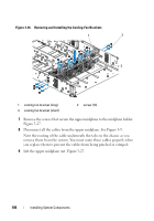
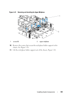
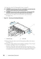
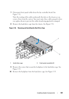
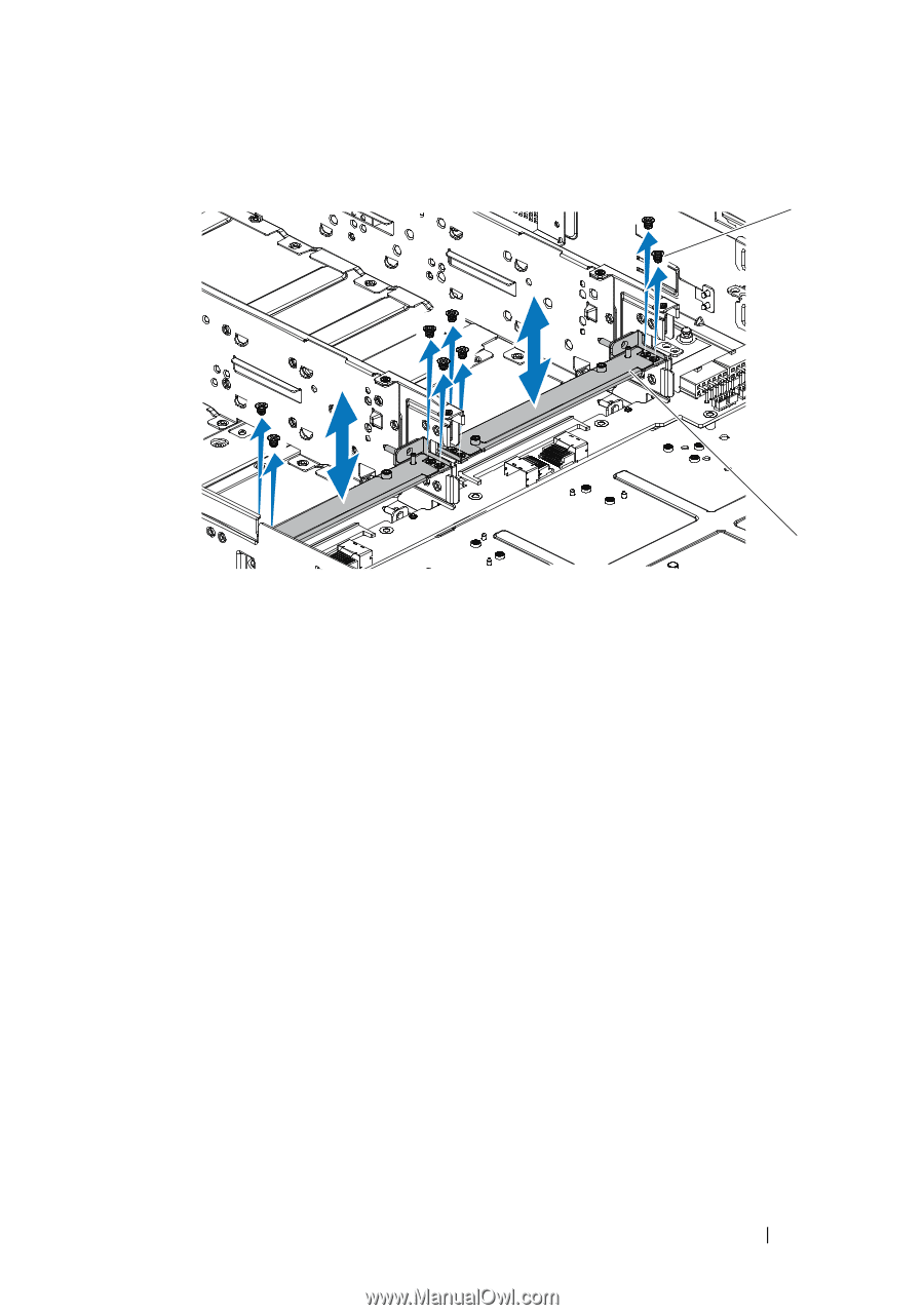
Figure 3-29. Removing and Installing the Mid-Plane Holder 1 2 1 screw (8) 2 mid-plane holder 14 Remove the screws that secure the lower midplane to the chassis. Figure 3-30. 15 Disconnect all the cables from the lower midplane. See Figure 5-9. Note the routing of the cable underneath the tabs on the chassis as you remove them from the system. You must route these cables properly when you replace them to prevent the cables from being pinched or crimped. 16 Lift the lower midplane out of the chassis. See Figure 3-30. Installing System Components 103
-
 1
1 -
2
-
3
-
4
-
5
-
6
-
7
-
8
-
9
-
10
-
11
-
12
-
13
-
14
-
15
-
16
-
17
-
18
-
19
-
20
-
21
-
22
-
23
-
24
-
25
-
26
-
27
-
28
-
29
-
30
-
31
-
32
-
33
-
34
-
35
-
36
-
37
-
38
-
39
-
40
-
41
-
42
-
43
-
44
-
45
-
46
-
47
-
48
-
49
-
50
-
51
-
52
-
53
-
54
-
55
-
56
-
57
-
58
-
59
-
60
-
61
-
62
-
63
-
64
-
65
-
66
-
67
-
68
-
69
-
70
-
71
-
72
-
73
-
74
-
75
-
76
-
77
-
78
-
79
-
80
-
81
-
82
-
83
-
84
-
85
-
86
-
87
-
88
-
89
-
90
-
91
-
92
-
93
-
94
-
95
-
96
-
97
-
 98
98 -
 99
99 -
 100
100 -
 101
101 -
 102
102 -
 103
103 -
 104
104 -
 105
105 -
 106
106 -
 107
107 -
 108
108 -
109
-
110
-
111
-
112
-
113
-
114
-
115
-
116
-
117
-
118
-
119
-
120
-
121
-
122
-
123
-
124
-
125
-
126
-
127
-
128
-
129
-
130
-
131
-
132
-
133
-
134
-
135
-
136
-
137
-
138
-
139
-
140
-
141
-
142
-
143
-
144
-
145
-
146
-
147
-
148
-
149
-
150
-
151
-
152
-
153
-
154
-
155
-
156
-
157
-
158
-
159
-
160
 |
 |
Installing System Components
103
Figure 3-29.
Removing and Installing the Mid-Plane Holder
14
Remove the screws that secure the lower midplane to the chassis.
Figure 3-30.
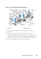
15
Disconnect all the cables from the lower midplane. See Figure 5-9.
Note the routing of the cable underneath the tabs on the chassis as you
remove them from the system. You must route these cables properly when
you replace them to prevent the cables from being pinched or crimped.
16
Lift the lower midplane out of the chassis. See Figure 3-30.
1
screw (8)
2
mid-plane holder
1
2