Dell PowerEdge C6100 Hardware Owner's Manual - Page 14
Front Panel-2.5 Hard Drives With Two System Boards, Indicator, Button, or Connector - chassis
 |
View all Dell PowerEdge C6100 manuals
Add to My Manuals
Save this manual to your list of manuals |
Page 14 highlights
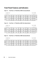
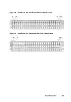
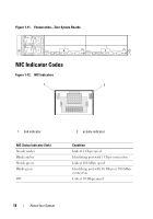
Figure 1-6. Front Panel-2.5" Hard Drives With Two System Boards 1 234 5 *6 7 89 4-11 4-10 4-9 4-8 4-7 4-6 4-5 4-4 4-3 4-2 4-1 4-0 2-11 2-10 2-9 2-8 2-7 2-6 2-5 2-4 2-3 2-2 2-1 2-0 Item Indicator, Button, Icon or Connector 1, 3, 7, 9 Power-on indicator/ power button (system boards 1, 2, 4, 3) 2, 4, 6, 8 System identification indicator/button (system boards 1, 2, 4, 3) Description The power-on indicator lights when the system power is on. The power button controls the DC power supply output to the system. NOTE: When powering on the system, the video monitor can take from several seconds to over 2 minutes to display an image, depending on the amount of memory installed in the system. NOTE: On ACPI-compliant operating systems, turning off the system using the power button causes the system to perform a graceful shutdown before power to the system is turned off. NOTE: To force an ungraceful shutdown, press and hold the power button for 5 seconds. The identification button can be used to locate a particular system and system board within a chassis. When the button is pushed, the blue system status indicator on the front and the back blink until the button is pushed again. 14 About Your System
-
 1
1 -
2
-
3
-
4
-
5
-
6
-
7
-
8
-
 9
9 -
 10
10 -
 11
11 -
 12
12 -
 13
13 -
 14
14 -
 15
15 -
 16
16 -
 17
17 -
 18
18 -
 19
19 -
20
-
21
-
22
-
23
-
24
-
25
-
26
-
27
-
28
-
29
-
30
-
31
-
32
-
33
-
34
-
35
-
36
-
37
-
38
-
39
-
40
-
41
-
42
-
43
-
44
-
45
-
46
-
47
-
48
-
49
-
50
-
51
-
52
-
53
-
54
-
55
-
56
-
57
-
58
-
59
-
60
-
61
-
62
-
63
-
64
-
65
-
66
-
67
-
68
-
69
-
70
-
71
-
72
-
73
-
74
-
75
-
76
-
77
-
78
-
79
-
80
-
81
-
82
-
83
-
84
-
85
-
86
-
87
-
88
-
89
-
90
-
91
-
92
-
93
-
94
-
95
-
96
-
97
-
98
-
99
-
100
-
101
-
102
-
103
-
104
-
105
-
106
-
107
-
108
-
109
-
110
-
111
-
112
-
113
-
114
-
115
-
116
-
117
-
118
-
119
-
120
-
121
-
122
-
123
-
124
-
125
-
126
-
127
-
128
-
129
-
130
-
131
-
132
-
133
-
134
-
135
-
136
-
137
-
138
-
139
-
140
-
141
-
142
-
143
-
144
-
145
-
146
-
147
-
148
-
149
-
150
-
151
-
152
-
153
-
154
-
155
-
156
-
157
-
158
-
159
-
160
 |
 |
