Dell PowerEdge C6100 Hardware Owner's Manual - Page 130
Backplane Connectors
 |
View all Dell PowerEdge C6100 manuals
Add to My Manuals
Save this manual to your list of manuals |
Page 130 highlights
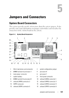
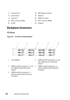
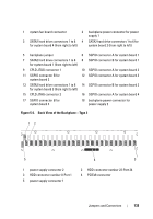
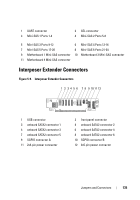
17 expansion slot 19 power button 21 serial port 23 NIC2 connector (RJ45) 25 ID LED 18 BMC debug connector 20 VGA port 22 KVM over IP port 24 NIC1 connector (RJ45) 26 USB port Backplane Connectors 3.5" drives Figure 5-2. Front View of the Backplane 1 2 3 4 5 1 3.5" backplane 2 SATA2 and SAS connectors 1, 2, and 3 for system board 1 (from top to bottom) 3 SATA2 and SAS connectors 1, 2, and 4 SATA2 and SAS connectors 1, 2, 3 for system board 2 (from top to and 3 for system board 3 (from top bottom) to bottom) 5 SATA2 and S AS connectors 1, 2, and 3 for system board 4 (from top to bottom) 130 Jumpers and Connectors
-
 1
1 -
2
-
3
-
4
-
5
-
6
-
7
-
8
-
9
-
10
-
11
-
12
-
13
-
14
-
15
-
16
-
17
-
18
-
19
-
20
-
21
-
22
-
23
-
24
-
25
-
26
-
27
-
28
-
29
-
30
-
31
-
32
-
33
-
34
-
35
-
36
-
37
-
38
-
39
-
40
-
41
-
42
-
43
-
44
-
45
-
46
-
47
-
48
-
49
-
50
-
51
-
52
-
53
-
54
-
55
-
56
-
57
-
58
-
59
-
60
-
61
-
62
-
63
-
64
-
65
-
66
-
67
-
68
-
69
-
70
-
71
-
72
-
73
-
74
-
75
-
76
-
77
-
78
-
79
-
80
-
81
-
82
-
83
-
84
-
85
-
86
-
87
-
88
-
89
-
90
-
91
-
92
-
93
-
94
-
95
-
96
-
97
-
98
-
99
-
100
-
101
-
102
-
103
-
104
-
105
-
106
-
107
-
108
-
109
-
110
-
111
-
112
-
113
-
114
-
115
-
116
-
117
-
118
-
119
-
120
-
121
-
122
-
123
-
124
-
 125
125 -
 126
126 -
 127
127 -
 128
128 -
 129
129 -
 130
130 -
 131
131 -
 132
132 -
 133
133 -
 134
134 -
 135
135 -
136
-
137
-
138
-
139
-
140
-
141
-
142
-
143
-
144
-
145
-
146
-
147
-
148
-
149
-
150
-
151
-
152
-
153
-
154
-
155
-
156
-
157
-
158
-
159
-
160
 |
 |

130
Jumpers and Connectors
Backplane Connectors
3.5" drives
Figure 5-2.
Front View of the Backplane
17
expansion slot
18
BMC debug connector
19
power button
20
VGA port
21
serial port
22
KVM over IP port
23
NIC2 connector (RJ45)
24
NIC1 connector (RJ45)
25
ID LED
26
USB port
1
3.5" backplane
2
SATA2 and SAS connectors 1, 2, and
3 for system board 1 (from top to
bottom)
3
SATA2 and SAS connectors 1, 2, and
3 for system board 2 (from top to
bottom)
4
SATA2 and SAS connectors 1, 2,
and 3 for system board 3 (from top
to bottom)
5
SATA2 and S AS connectors 1, 2,
and 3 for system board 4 (from top
to bottom)
1
2
3
4
5