Dell PowerEdge C6100 Hardware Owner's Manual - Page 72
Expansion-Card Connector, Removing the Expansion-Card Connector
 |
View all Dell PowerEdge C6100 manuals
Add to My Manuals
Save this manual to your list of manuals |
Page 72 highlights
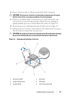
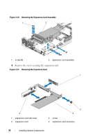
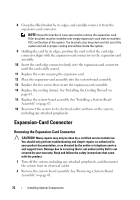
8 Grasp the filler bracket by its edges, and carefully remove it from the expansion-card connector. NOTE: Keep this bracket in case you need to remove the expansion card. Filler brackets must be installed over empty expansion-card slots to maintain FCC certification of the system. The brackets also keep dust and dirt out of the system and aid in proper cooling and airflow inside the system. 9 Holding the card by its edges, position the card so that the card-edge connector aligns with the expansion-card connector on the expansion-card assembly. 10 Insert the card-edge connector firmly into the expansion-card connector until the card is fully seated. 11 Replace the screw securing the expansion card. 12 Place the expansion-card assembly into the system-board assembly. 13 Replace the five screws that secure the expansion-card assembly. 14 Replace the cooling shroud. See "Installing the Cooling Shroud" on page 64. 15 Replace the system-board assembly. See "Installing a System-Board Assembly" on page 62. 16 Reconnect the system to its electrical outlet and turn on the system, including any attached peripherals. Expansion-Card Connector Removing the Expansion-Card Connector CAUTION: Many repairs may only be done by a certified service technician. You should only perform troubleshooting and simple repairs as authorized in your product documentation, or as directed by the online or telephone service and support team. Damage due to servicing that is not authorized by Dell is not covered by your warranty. Read and follow the safety instructions that came with the product. 1 Turn off the system, including any attached peripherals, and disconnect the system from its electrical outlet. 2 Remove the system-board assembly. See "Removing a System-Board Assembly" on page 61. 72 Installing System Components
-
 1
1 -
2
-
3
-
4
-
5
-
6
-
7
-
8
-
9
-
10
-
11
-
12
-
13
-
14
-
15
-
16
-
17
-
18
-
19
-
20
-
21
-
22
-
23
-
24
-
25
-
26
-
27
-
28
-
29
-
30
-
31
-
32
-
33
-
34
-
35
-
36
-
37
-
38
-
39
-
40
-
41
-
42
-
43
-
44
-
45
-
46
-
47
-
48
-
49
-
50
-
51
-
52
-
53
-
54
-
55
-
56
-
57
-
58
-
59
-
60
-
61
-
62
-
63
-
64
-
65
-
66
-
 67
67 -
 68
68 -
 69
69 -
 70
70 -
 71
71 -
 72
72 -
 73
73 -
 74
74 -
 75
75 -
 76
76 -
 77
77 -
78
-
79
-
80
-
81
-
82
-
83
-
84
-
85
-
86
-
87
-
88
-
89
-
90
-
91
-
92
-
93
-
94
-
95
-
96
-
97
-
98
-
99
-
100
-
101
-
102
-
103
-
104
-
105
-
106
-
107
-
108
-
109
-
110
-
111
-
112
-
113
-
114
-
115
-
116
-
117
-
118
-
119
-
120
-
121
-
122
-
123
-
124
-
125
-
126
-
127
-
128
-
129
-
130
-
131
-
132
-
133
-
134
-
135
-
136
-
137
-
138
-
139
-
140
-
141
-
142
-
143
-
144
-
145
-
146
-
147
-
148
-
149
-
150
-
151
-
152
-
153
-
154
-
155
-
156
-
157
-
158
-
159
-
160
 |
 |