Dell Vostro 220 Service Manual - Page 105
at each end of the module., If you insert the module correctly
 |
UPC - 884116011958
View all Dell Vostro 220 manuals
Add to My Manuals
Save this manual to your list of manuals |
Page 105 highlights
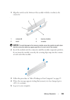
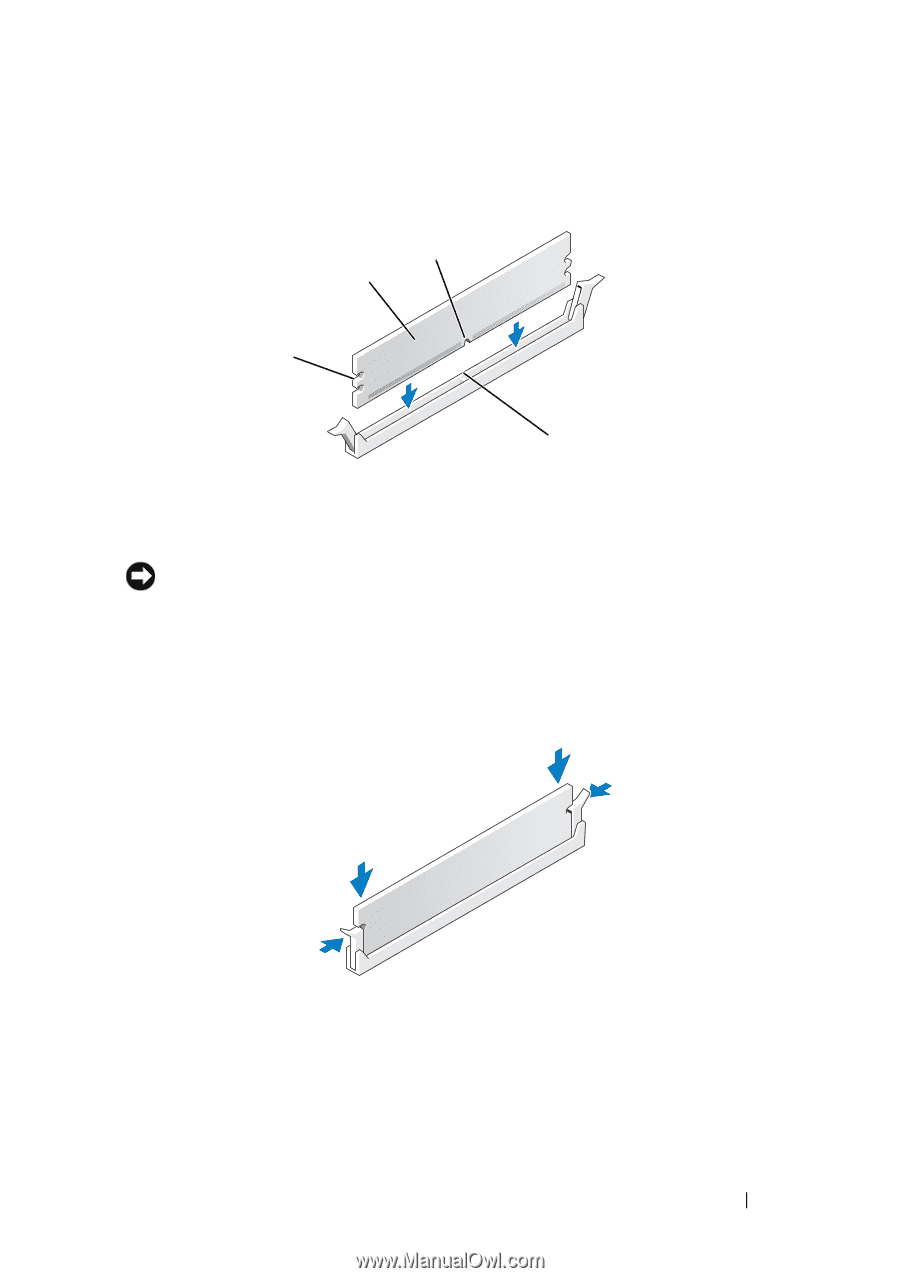
1 Align the notch on the bottom of the module with the crossbar in the connector. . 3 2 1 4 1 cutouts (2) 3 notch 2 memory module 4 crossbar NOTICE: To avoid damage to the memory module, press the module straight down into the connector while you apply equal force to each end of the module. 2 Insert the module into the connector until the module snaps into position. If you insert the module correctly, the securing clips snap into the cutouts at each end of the module. 3 Follow the procedure in "After Working on Your Computer" on page 45. 4 When the message appears stating that memory size has changed, press to continue. 5 Log on to your computer. Memory Module(s) 105
-
 1
1 -
2
-
3
-
4
-
5
-
6
-
7
-
8
-
9
-
10
-
11
-
12
-
13
-
14
-
15
-
16
-
17
-
18
-
19
-
20
-
21
-
22
-
23
-
24
-
25
-
26
-
27
-
28
-
29
-
30
-
31
-
32
-
33
-
34
-
35
-
36
-
37
-
38
-
39
-
40
-
41
-
42
-
43
-
44
-
45
-
46
-
47
-
48
-
49
-
50
-
51
-
52
-
53
-
54
-
55
-
56
-
57
-
58
-
59
-
60
-
61
-
62
-
63
-
64
-
65
-
66
-
67
-
68
-
69
-
70
-
71
-
72
-
73
-
74
-
75
-
76
-
77
-
78
-
79
-
80
-
81
-
82
-
83
-
84
-
85
-
86
-
87
-
88
-
89
-
90
-
91
-
92
-
93
-
94
-
95
-
96
-
97
-
98
-
99
-
 100
100 -
 101
101 -
 102
102 -
 103
103 -
 104
104 -
 105
105 -
 106
106 -
 107
107 -
 108
108 -
 109
109 -
 110
110 -
111
-
112
-
113
-
114
-
115
-
116
-
117
-
118
-
119
-
120
-
121
-
122
-
123
-
124
-
125
-
126
-
127
-
128
-
129
-
130
-
131
-
132
-
133
-
134
-
135
-
136
-
137
-
138
 |
 |
Memory Module(s)
105
1
Align the notch on the bottom of the module with the crossbar in the
connector.
.
NOTICE:
To avoid damage to the memory module, press the module straight down
into the connector while you apply equal force to each end of the module.
2
Insert the module into the connector until the module snaps into position.
If you insert the module correctly, the securing clips snap into the cutouts
at each end of the module.
3
Follow the procedure in "After Working on Your Computer" on page45.
4
When the message appears stating that memory size has changed, press
<F1> to continue.
5
Log on to your computer.
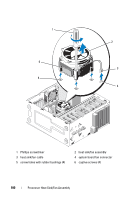
1
cutouts (2)
2
memory module
3
notch
4
crossbar
3
2
1
4