Dell Vostro 220 Service Manual - Page 45
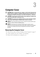
After Working on Your Computer
 |
UPC - 884116011958
View all Dell Vostro 220 manuals
Add to My Manuals
Save this manual to your list of manuals |
Page 45 highlights
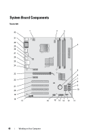
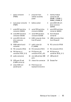
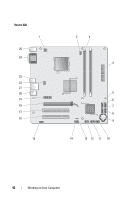
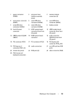
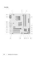
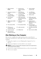
1 power connector (PWR2) 4 main power connector (PWR1) 7 serial ATA drive connector (SATA3) 10 front I/O panel connector 13 CMOS jumper (CLEAR CMOS) 2 processor heat sink/fan assembly power 5 serial ATA drive connector (SATA2) 8 serial ATA drive connector (SATA0) 11 USB1 system board connector (from front I/O panel) 14 USB3 system board connector 16 PCI connector (PCI1) 17 PCI connector (PCI2) 19 PCI Express x1 connector (PCIE_X1) 22 chassis fan power 25 PS/2 mouse and keyboard connectors 20 audio connectors 23 USB ports (2) 3 memory module connectors (2) 6 serial ATA drive connector (SATA1) 9 battery socket 12 USB2 system board connector (from front I/O panel) 15 audio connector (AUDIO1) (from front I/O panel) 18 PCI Express x16 connector (PCIE_x16) 21 one LAN and two USB ports 24 video connector (VGA) After Working on Your Computer After you have completed any replacement procedures, ensure that you connect any external devices, cards, cables, and so on, before turning on your computer. 1 Replace the computer cover (see "Replacing the Computer Cover" on page 48). 2 Connect any telephone or network cables to your computer. NOTICE: To connect a network cable, first plug the cable into the network device and then plug it into the computer. 3 Connect your computer and all attached devices to their electrical outlets. 4 Turn on your computer. Working on Your Computer 45
-
 1
1 -
2
-
3
-
4
-
5
-
6
-
7
-
8
-
9
-
10
-
11
-
12
-
13
-
14
-
15
-
16
-
17
-
18
-
19
-
20
-
21
-
22
-
23
-
24
-
25
-
26
-
27
-
28
-
29
-
30
-
31
-
32
-
33
-
34
-
35
-
36
-
37
-
38
-
39
-
 40
40 -
 41
41 -
 42
42 -
 43
43 -
 44
44 -
 45
45 -
 46
46 -
 47
47 -
 48
48 -
 49
49 -
 50
50 -
51
-
52
-
53
-
54
-
55
-
56
-
57
-
58
-
59
-
60
-
61
-
62
-
63
-
64
-
65
-
66
-
67
-
68
-
69
-
70
-
71
-
72
-
73
-
74
-
75
-
76
-
77
-
78
-
79
-
80
-
81
-
82
-
83
-
84
-
85
-
86
-
87
-
88
-
89
-
90
-
91
-
92
-
93
-
94
-
95
-
96
-
97
-
98
-
99
-
100
-
101
-
102
-
103
-
104
-
105
-
106
-
107
-
108
-
109
-
110
-
111
-
112
-
113
-
114
-
115
-
116
-
117
-
118
-
119
-
120
-
121
-
122
-
123
-
124
-
125
-
126
-
127
-
128
-
129
-
130
-
131
-
132
-
133
-
134
-
135
-
136
-
137
-
138
 |
 |