Dell Vostro 220 Service Manual - Page 81
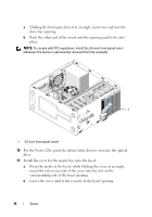
Disconnect the data cable from the system board see System Board, Components
 |
UPC - 884116011958
View all Dell Vostro 220 manuals
Add to My Manuals
Save this manual to your list of manuals |
Page 81 highlights
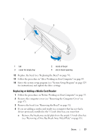
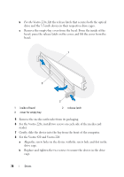
1 2 5 4 3 1 screws (2) 3 optical drive 5 power cable 2 screw holes (4) 4 data cable 5 For the Vostro 420 and Vostro 220, remove the two screws securing the optical drive to the drive cage. 6 Slide the optical drive out through the front of the computer. 7 If you are installing a replacement drive, skip to step 5 in "Replacing or Adding an Optical Drive" on page 82. If you are removing this drive permanently and the drive bay is to remain empty, proceed to step 8. 8 Disconnect the data cable from the system board (see "System Board Components" on page 40), and remove the cable from the computer. 9 For the Vostro 420 and Vostro 220, use two screws to attach a 5.25-inch front-panel insert to the front of the empty bay. Drives 81
-
 1
1 -
2
-
3
-
4
-
5
-
6
-
7
-
8
-
9
-
10
-
11
-
12
-
13
-
14
-
15
-
16
-
17
-
18
-
19
-
20
-
21
-
22
-
23
-
24
-
25
-
26
-
27
-
28
-
29
-
30
-
31
-
32
-
33
-
34
-
35
-
36
-
37
-
38
-
39
-
40
-
41
-
42
-
43
-
44
-
45
-
46
-
47
-
48
-
49
-
50
-
51
-
52
-
53
-
54
-
55
-
56
-
57
-
58
-
59
-
60
-
61
-
62
-
63
-
64
-
65
-
66
-
67
-
68
-
69
-
70
-
71
-
72
-
73
-
74
-
75
-
 76
76 -
 77
77 -
 78
78 -
 79
79 -
 80
80 -
 81
81 -
 82
82 -
 83
83 -
 84
84 -
 85
85 -
 86
86 -
87
-
88
-
89
-
90
-
91
-
92
-
93
-
94
-
95
-
96
-
97
-
98
-
99
-
100
-
101
-
102
-
103
-
104
-
105
-
106
-
107
-
108
-
109
-
110
-
111
-
112
-
113
-
114
-
115
-
116
-
117
-
118
-
119
-
120
-
121
-
122
-
123
-
124
-
125
-
126
-
127
-
128
-
129
-
130
-
131
-
132
-
133
-
134
-
135
-
136
-
137
-
138
 |
 |

Drives
81
5
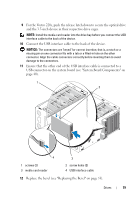
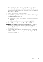
For the Vostro 420 and Vostro 220, remove the two screws securing the
optical drive to the drive cage.
6
Slide the optical drive out through the front of the computer.
7
If you are installing a replacement drive
, skip to step 5 in "Replacing or
Adding an Optical Drive" on page 82.
If you are removing this drive permanently and the drive bay is to remain
empty
, proceed to step 8.
8
Disconnect the data cable from the system board (see "System Board
Components" on page 40), and remove the cable from the computer.
9
For the Vostro 420 and Vostro 220, use two screws to attach a 5.25-inch
front-panel insert to the front of the empty bay.
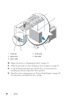
1
screws (2)
2
screw holes (4)
3
optical drive
4
data cable
5
power cable
4
5
3
1
2