Dell Vostro 220 Service Manual - Page 72
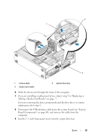
Connect the power and data cables to the back of the drive., connector labeled SATA0, SATA1
 |
UPC - 884116011958
View all Dell Vostro 220 manuals
Add to My Manuals
Save this manual to your list of manuals |
Page 72 highlights
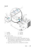
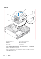
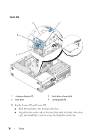
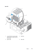
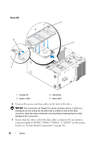
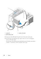
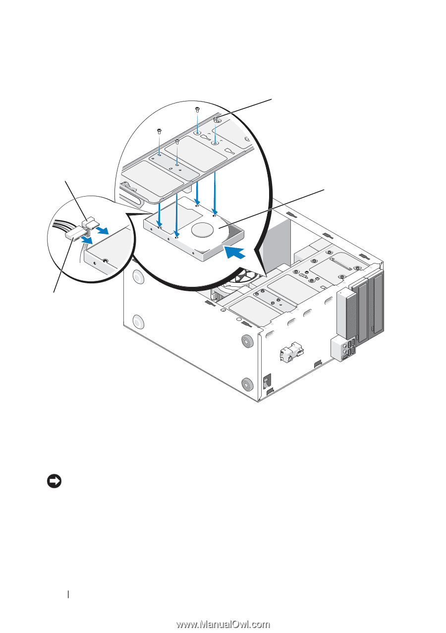
Vostro 220 4 3 1 2 1 screws (4) 3 power cable 2 hard drive 4 data cable 6 Connect the power and data cables to the back of the drive. NOTICE: The connectors are "keyed" for correct insertion; that is, a notch or a missing pin on one connector fits with a tab or a filled-in hole on the other connector. Align the cable connectors correctly before inserting them to avoid damage to the connectors. 7 Ensure that the other end of the data cable is connected to an interface connector labeled "SATA0," "SATA1," "SATA2," or "SATA3" on the system board (see "System Board Components" on page 40). 72 Drives
-
 1
1 -
2
-
3
-
4
-
5
-
6
-
7
-
8
-
9
-
10
-
11
-
12
-
13
-
14
-
15
-
16
-
17
-
18
-
19
-
20
-
21
-
22
-
23
-
24
-
25
-
26
-
27
-
28
-
29
-
30
-
31
-
32
-
33
-
34
-
35
-
36
-
37
-
38
-
39
-
40
-
41
-
42
-
43
-
44
-
45
-
46
-
47
-
48
-
49
-
50
-
51
-
52
-
53
-
54
-
55
-
56
-
57
-
58
-
59
-
60
-
61
-
62
-
63
-
64
-
65
-
66
-
 67
67 -
 68
68 -
 69
69 -
 70
70 -
 71
71 -
 72
72 -
 73
73 -
 74
74 -
 75
75 -
 76
76 -
 77
77 -
78
-
79
-
80
-
81
-
82
-
83
-
84
-
85
-
86
-
87
-
88
-
89
-
90
-
91
-
92
-
93
-
94
-
95
-
96
-
97
-
98
-
99
-
100
-
101
-
102
-
103
-
104
-
105
-
106
-
107
-
108
-
109
-
110
-
111
-
112
-
113
-
114
-
115
-
116
-
117
-
118
-
119
-
120
-
121
-
122
-
123
-
124
-
125
-
126
-
127
-
128
-
129
-
130
-
131
-
132
-
133
-
134
-
135
-
136
-
137
-
138
 |
 |
72
Drives
Vostro 220
6
Connect the power and data cables to the back of the drive.
NOTICE:
The connectors are "keyed" for correct insertion; that is, a notch or a
missing pin on one connector fits with a tab or a filled-in hole on the other
connector. Align the cable connectors correctly before inserting them to avoid
damage to the connectors.
7
Ensure that the other end of the data cable is connected to an interface
connector labeled "SATA0," "SATA1," "SATA2," or "SATA3" on the system
board (see "System Board Components" on page 40).
1
screws (4)
2
hard drive
3
power cable
4
data cable
2
1
4
3