Dell Vostro 220 Service Manual - Page 107
Power Supply, Removing the Power Supply - power supply replacement
 |
UPC - 884116011958
View all Dell Vostro 220 manuals
Add to My Manuals
Save this manual to your list of manuals |
Page 107 highlights
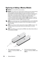
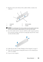
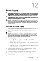
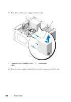
Power Supply CAUTION: Before working inside your computer, read the safety information that shipped with your computer. For additional safety best practices information, see the Regulatory Compliance Homepage at www.dell.com/regulatory_compliance. CAUTION: To guard against electrical shock, always unplug your computer from the electrical outlet before removing the cover. NOTICE: The procedure for removing and replacing the power supply is identical (except where noted) for the Vostro 420, Vostro 220, and Vostro 220s computers; the illustrations provided are for example only and may not represent your particular computer precisely. Removing the Power Supply 1 Follow the procedures in "Before Working on Your Computer" on page 35. 2 Remove the computer cover (see "Removing the Computer Cover" on page 47). NOTICE: Note the routing of the DC power cables underneath the metal routing clips (if present) in the computer chassis as you remove them from the system board and drives. You must reroute these cables properly when you reinstall the power supply to prevent them from being pinched or crimped. 3 For the Vostro 220s: a Remove the chassis support bracket (see "Removing the Chassis Support Bracket" on page 55). b Slide the optical drive forward far enough to gain access to the PWR1 connector on the system board. c Remove any installed PCI or PCI Express cards (see "Removing a PCI or PCI Express Card" on page 59). 4 Disconnect the DC power cables from the system board (see "System Board Components" on page 40) and the drives. 5 Disengage the cables from the routing clips (if present) on the chassis. 6 Remove the screws that attach the power supply to the back of the computer chassis. Power Supply 107
-
 1
1 -
2
-
3
-
4
-
5
-
6
-
7
-
8
-
9
-
10
-
11
-
12
-
13
-
14
-
15
-
16
-
17
-
18
-
19
-
20
-
21
-
22
-
23
-
24
-
25
-
26
-
27
-
28
-
29
-
30
-
31
-
32
-
33
-
34
-
35
-
36
-
37
-
38
-
39
-
40
-
41
-
42
-
43
-
44
-
45
-
46
-
47
-
48
-
49
-
50
-
51
-
52
-
53
-
54
-
55
-
56
-
57
-
58
-
59
-
60
-
61
-
62
-
63
-
64
-
65
-
66
-
67
-
68
-
69
-
70
-
71
-
72
-
73
-
74
-
75
-
76
-
77
-
78
-
79
-
80
-
81
-
82
-
83
-
84
-
85
-
86
-
87
-
88
-
89
-
90
-
91
-
92
-
93
-
94
-
95
-
96
-
97
-
98
-
99
-
100
-
101
-
 102
102 -
 103
103 -
 104
104 -
 105
105 -
 106
106 -
 107
107 -
 108
108 -
 109
109 -
 110
110 -
 111
111 -
 112
112 -
113
-
114
-
115
-
116
-
117
-
118
-
119
-
120
-
121
-
122
-
123
-
124
-
125
-
126
-
127
-
128
-
129
-
130
-
131
-
132
-
133
-
134
-
135
-
136
-
137
-
138
 |
 |