Dell Vostro 220 Service Manual - Page 83
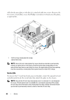
drive cage., Align the screw slots in the optical drive with the screw slots on
 |
UPC - 884116011958
View all Dell Vostro 220 manuals
Add to My Manuals
Save this manual to your list of manuals |
Page 83 highlights
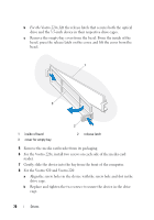
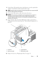
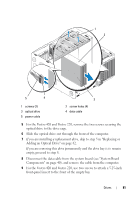
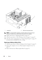
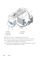
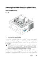
4 If you are adding an optical drive in a bay that has not had a device previously installed in it, remove the break-away metal plate (front-panel insert) from the empty drive bay (see "Removing a Drive Bay Break-Away Metal Plate" on page 85). 5 Remove the optical drive from its packaging. 6 Gently slide the optical drive into the bay from the front of the computer. 7 For the Vostro 420 and Vostro 220: a Align the screw slots in the optical drive with the screw slots on the drive cage. b Replace and tighten the two screws securing the optical drive. 8 Connect the power cable and data cable to the back of the drive. NOTICE: The connectors are "keyed" for correct insertion; that is, a notch or a missing pin on one connector fits with a tab or a filled-in hole on the other connector. Align the cable connectors correctly before inserting them to avoid damage to the connectors. 9 Ensure that the other end of the data cable is connected to the SATA4, SATA5, or SATA6 connector on the system board (see "System Board Components" on page 40. Drives 83
-
 1
1 -
2
-
3
-
4
-
5
-
6
-
7
-
8
-
9
-
10
-
11
-
12
-
13
-
14
-
15
-
16
-
17
-
18
-
19
-
20
-
21
-
22
-
23
-
24
-
25
-
26
-
27
-
28
-
29
-
30
-
31
-
32
-
33
-
34
-
35
-
36
-
37
-
38
-
39
-
40
-
41
-
42
-
43
-
44
-
45
-
46
-
47
-
48
-
49
-
50
-
51
-
52
-
53
-
54
-
55
-
56
-
57
-
58
-
59
-
60
-
61
-
62
-
63
-
64
-
65
-
66
-
67
-
68
-
69
-
70
-
71
-
72
-
73
-
74
-
75
-
76
-
77
-
 78
78 -
 79
79 -
 80
80 -
 81
81 -
 82
82 -
 83
83 -
 84
84 -
 85
85 -
 86
86 -
 87
87 -
 88
88 -
89
-
90
-
91
-
92
-
93
-
94
-
95
-
96
-
97
-
98
-
99
-
100
-
101
-
102
-
103
-
104
-
105
-
106
-
107
-
108
-
109
-
110
-
111
-
112
-
113
-
114
-
115
-
116
-
117
-
118
-
119
-
120
-
121
-
122
-
123
-
124
-
125
-
126
-
127
-
128
-
129
-
130
-
131
-
132
-
133
-
134
-
135
-
136
-
137
-
138
 |
 |
