Dell Vostro 220 Service Manual - Page 127
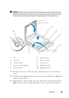
notches on the socket., Align the pin-1 corners of the processor and socket, and set the processor
 |
UPC - 884116011958
View all Dell Vostro 220 manuals
Add to My Manuals
Save this manual to your list of manuals |
Page 127 highlights
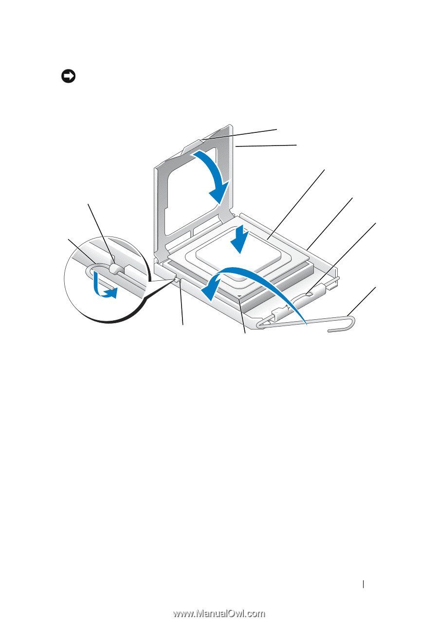
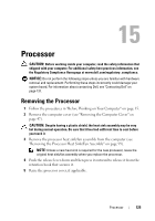
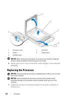
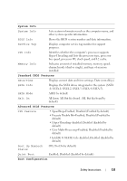
NOTICE: Socket pins are delicate. To avoid damage, ensure that the processor is aligned properly with the socket, and do not use excessive force when you install the processor. Be careful not to touch or bend the pins on the system board. 1 2 3 10 9 4 5 6 8 7 1 tab 3 processor 5 retention latch 7 processor pin-1 indicator 9 retention hook 2 processor cover 4 processor socket 6 release lever 8 alignment notch 10 alignment notch 2 Pivot the release lever fully and ensure that the processor cover remains raised. 3 Orient the two alignment notches on the processor with the two alignment notches on the socket. 4 Align the pin-1 corners of the processor and socket, and set the processor lightly in the socket, ensuring that the processor is positioned correctly. Processor 127
-
 1
1 -
2
-
3
-
4
-
5
-
6
-
7
-
8
-
9
-
10
-
11
-
12
-
13
-
14
-
15
-
16
-
17
-
18
-
19
-
20
-
21
-
22
-
23
-
24
-
25
-
26
-
27
-
28
-
29
-
30
-
31
-
32
-
33
-
34
-
35
-
36
-
37
-
38
-
39
-
40
-
41
-
42
-
43
-
44
-
45
-
46
-
47
-
48
-
49
-
50
-
51
-
52
-
53
-
54
-
55
-
56
-
57
-
58
-
59
-
60
-
61
-
62
-
63
-
64
-
65
-
66
-
67
-
68
-
69
-
70
-
71
-
72
-
73
-
74
-
75
-
76
-
77
-
78
-
79
-
80
-
81
-
82
-
83
-
84
-
85
-
86
-
87
-
88
-
89
-
90
-
91
-
92
-
93
-
94
-
95
-
96
-
97
-
98
-
99
-
100
-
101
-
102
-
103
-
104
-
105
-
106
-
107
-
108
-
109
-
110
-
111
-
112
-
113
-
114
-
115
-
116
-
117
-
118
-
119
-
120
-
121
-
 122
122 -
 123
123 -
 124
124 -
 125
125 -
 126
126 -
 127
127 -
 128
128 -
 129
129 -
 130
130 -
 131
131 -
 132
132 -
133
-
134
-
135
-
136
-
137
-
138
 |
 |