Dell Vostro 220 Service Manual - Page 120
Disconnect any additional cables from the system board.
 |
UPC - 884116011958
View all Dell Vostro 220 manuals
Add to My Manuals
Save this manual to your list of manuals |
Page 120 highlights
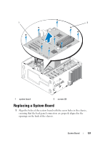
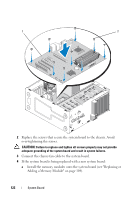
b Remove the memory modules from the system board (see "Replacing or Adding a Memory Module" on page 104) and place them individually into antistatic packaging. c Remove the processor from the system board (see "Removing the Processor" on page 125) and place it into antistatic packaging. 9 Disconnect the chassis fan cable from the system board. 10 Disconnect any additional cables from the system board. 11 Remove the screws that secure the system board to the computer chassis. CAUTION: The system board is extremely fragile. Exercise great care when handling the system board. 12 Carefully lift the system board out of the computer chassis and place it into antistatic packaging. 120 System Board
-
 1
1 -
2
-
3
-
4
-
5
-
6
-
7
-
8
-
9
-
10
-
11
-
12
-
13
-
14
-
15
-
16
-
17
-
18
-
19
-
20
-
21
-
22
-
23
-
24
-
25
-
26
-
27
-
28
-
29
-
30
-
31
-
32
-
33
-
34
-
35
-
36
-
37
-
38
-
39
-
40
-
41
-
42
-
43
-
44
-
45
-
46
-
47
-
48
-
49
-
50
-
51
-
52
-
53
-
54
-
55
-
56
-
57
-
58
-
59
-
60
-
61
-
62
-
63
-
64
-
65
-
66
-
67
-
68
-
69
-
70
-
71
-
72
-
73
-
74
-
75
-
76
-
77
-
78
-
79
-
80
-
81
-
82
-
83
-
84
-
85
-
86
-
87
-
88
-
89
-
90
-
91
-
92
-
93
-
94
-
95
-
96
-
97
-
98
-
99
-
100
-
101
-
102
-
103
-
104
-
105
-
106
-
107
-
108
-
109
-
110
-
111
-
112
-
113
-
114
-
 115
115 -
 116
116 -
 117
117 -
 118
118 -
 119
119 -
 120
120 -
 121
121 -
 122
122 -
 123
123 -
 124
124 -
 125
125 -
126
-
127
-
128
-
129
-
130
-
131
-
132
-
133
-
134
-
135
-
136
-
137
-
138
 |
 |
120
System Board
b
Remove the memory modules from the system board (see "Replacing
or Adding a Memory Module" on page 104) and place them
individually into antistatic packaging.
c
Remove the processor from the system board (see "Removing the
Processor" on page 125) and place it into antistatic packaging.
9
Disconnect the chassis fan cable from the system board.
10
Disconnect any additional cables from the system board.
11
Remove the screws that secure the system board to the computer chassis.
CAUTION:
The system board is extremely fragile. Exercise great care when
handling the system board.
12
Carefully lift the system board out of the computer chassis and place it
into antistatic packaging.