Epson ActionLaser 1100 User Manual - Page 58
Inferface, A-6 Technical Specifications
 |
View all Epson ActionLaser 1100 manuals
Add to My Manuals
Save this manual to your list of manuals |
Page 58 highlights
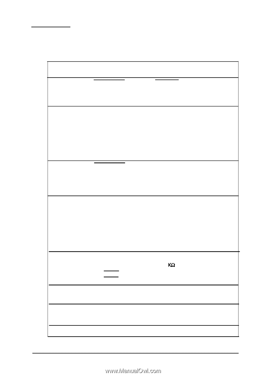
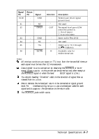
Inferface The parallel interface connector pin assignments and a description of the interface signals are shown in the table below. Signal Pin 1 2 3 4 5 6 7 8 9 10 11 12 13 14 15 16 17 18 Return Pin 19 20 21 22 23 24 25 26 27 28 29 30 - - - - - Signal STROBE Direction IN DATA 1 IN DATA 2 IN DATA 3 IN DATA 4 IN DATA 5 IN DATA 6 IN DATA 7 IN DATA 8 IN ACKNLG OUT BUSY OUT PE SLCT AUTO FEED NC GND CHASSIS GND NC OUT OUT IN - - - - Description STROBE pulse to read data. Pulse width must be at least 0.5 µs at the receiving terminal. These signals represent parallel data bits 1 to 8, respectively. Each signal is at HIGH level when data is logical 1 and LOW when it is logical 0. About a 1-10-µs pulse width. LOW indicates data has been received and the printer is ready to accept more data. A HIGH signal indicates that the printer cannot receive data. The signal goes HIGH in the following cases. 1. During printing 2. During a printer-error state A HIGH signal indicates the printer is out of paper Pulled up to +5v through 3.3 resistance. Not used Not used Logic ground level Printer's chassis ground, which is connected to the signal ground. Not used A-6 Technical Specifications
-
 1
1 -
2
-
3
-
4
-
5
-
6
-
7
-
8
-
9
-
10
-
11
-
12
-
13
-
14
-
15
-
16
-
17
-
18
-
19
-
20
-
21
-
22
-
23
-
24
-
25
-
26
-
27
-
28
-
29
-
30
-
31
-
32
-
33
-
34
-
35
-
36
-
37
-
38
-
39
-
40
-
41
-
42
-
43
-
44
-
45
-
46
-
47
-
48
-
49
-
50
-
51
-
52
-
 53
53 -
 54
54 -
 55
55 -
 56
56 -
 57
57 -
 58
58 -
 59
59 -
 60
60 -
 61
61 -
 62
62 -
 63
63 -
64
-
65
-
66
-
67
-
68
-
69
-
70
-
71
-
72
-
73
-
74
-
75
-
76
-
77
-
78
-
79
-
80
-
81
-
82
-
83
-
84
-
85
-
86
-
87
-
88
-
89
 |
 |