Fluke 199C/S FE 192,196,199 C Users Manual
Fluke 199C/S Manual
 |
View all Fluke 199C/S manuals
Add to My Manuals
Save this manual to your list of manuals |
Fluke 199C/S manual content summary:
- Fluke 199C/S | FE 192,196,199 C Users Manual - Page 1
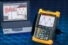
Fluke 192B - 196B/C - 199B/C ScopeMeter 4822 872 30601 October 2002 Rev. 2, 12/04 © 2002 Fluke Corporation. All rights reserved. Printed in the Netherlands. All product names are trademarks of their respective companies. Users Manual - Fluke 199C/S | FE 192,196,199 C Users Manual - Page 2
- Fluke 199C/S | FE 192,196,199 C Users Manual - Page 3
the date of shipment. Parts, product repairs and services are warranted for 90 days. This warranty extends only to the original buyer or end-user customer of a Fluke authorized reseller, and does not apply to fuses, disposable batteries or to any product which, in Fluke's opinion, has been misused - Fluke 199C/S | FE 192,196,199 C Users Manual - Page 4
SERVICE CENTERS To locate an authorized service center, visit us on the World Wide Web: http://www.fluke.com or call Fluke using any of the phone numbers listed below: +1-888-993-5853 in U.S.A. and Canada +31-40-2675200 in Europe +1-425-446-5500 from other countries - Fluke 199C/S | FE 192,196,199 C Users Manual - Page 5
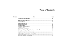
the Test Tool Kit 2 Safety Information: Read First 4 1 Using The Scope...7 Powering the Test Tool 7 Resetting the Test Tool 8 Navigating a Menu ...9 Hiding Key Labels and Menus 10 Input Connections ...10 Making Scope Connections 11 Displaying an Unknown Signal with Connect-and-View 12 - Fluke 199C/S | FE 192,196,199 C Users Manual - Page 6
Fluke 192B - 196B/C - 199B/C Users Manual Analyzing Waveforms ...25 2 Using The Multimeter 27 Making Meter Connections 27 Making Multimeter Measurements 28 Freezing the Readings 31 Selecting Auto/Manual Recording Scope Waveforms In Deep Memory (Scope Record 37 Analyzing a TrendPlot or Scope - Fluke 199C/S | FE 192,196,199 C Users Manual - Page 7
the Auto Set Options 81 8 Maintaining the Test Tool 83 Cleaning the Test Tool 83 Storing the Test Tool...83 Charging the Batteries 84 Extending Battery Operation Time 85 Replacing the NiMH Battery Pack BP190 86 Calibrating the Voltage Probes 86 Displaying Calibration Information 88 iii - Fluke 199C/S | FE 192,196,199 C Users Manual - Page 8
Fluke 192B - 196B/C - 199B/C Users Manual Parts and Accessories 88 Troubleshooting ...93 9 Specifications ...95 Introduction ...95 Dual Input Oscilloscope 96 Automatic Scope Measurements 98 Meter ...102 DMM Measurements on Meter Inputs 102 Recorder ...104 Zoom, Replay and Cursors 105 - Fluke 199C/S | FE 192,196,199 C Users Manual - Page 9
Declaration of Conformity for Fluke 192B - 196B/C - 199B/C ScopeMeter® test tools Manufacturer Fluke Industrial B.V. Lelyweg 1 7602 EA Almelo The Netherlands Statement of Conformity Based on test results using appropriate standards, the product is in conformity with Electromagnetic Compatibility - Fluke 199C/S | FE 192,196,199 C Users Manual - Page 10
Fluke 192B - 196B/C - 199B/C Users Manual Unpacking the Test Tool Kit The following items are included in your test tool kit: 1 2 e (2x) (1x) f (2x) b a (2x) c (2x) (2x) d Note When new, the rechargeable NiMH battery is not fully charged. See Chapter 8. 6 7 3 4 9 10 11 b (2x) a 5 8 - Fluke 199C/S | FE 192,196,199 C Users Manual - Page 11
6 Getting Started Manual 7 CD ROM with Users Manual (multi-language) 8 Shipment box (basic version only) Unpacking the Test Tool Kit Fluke 192B, 196B/C and 199B/C S versions include also the following items: # Description 9 Optically Isolated USB Adapter/Cable 10 FlukeView® ScopeMeter® Software for - Fluke 199C/S | FE 192,196,199 C Users Manual - Page 12
or fire: • Use only the Fluke power supply, Model BC190 (Battery Charger / Power Adapter). • Before use check that the selected/indicated range on the BC190 matches the local line power voltage and frequency. • For the BC190/808 universal Battery Charger / Power Adapter) only use line cords that - Fluke 199C/S | FE 192,196,199 C Users Manual - Page 13
of more than 4800 VA: • Use only insulated voltage probes, test leads and adapters supplied with the test tool, or indicated by Fluke as suitable for the Fluke190 ScopeMeter series. • Before use, inspect voltage probes, test leads and accessories for mechanical damage and replace when damaged - Fluke 199C/S | FE 192,196,199 C Users Manual - Page 14
Fluke 192B - 196B/C - 199B/C Users Manual The terms 'Isolated' or 'Electrically floating' are used in this manual to indicate a replace damaged test leads! Whenever it is likely that safety has been impaired, the test tool must be turned off and disconnected from the line power. The matter - Fluke 199C/S | FE 192,196,199 C Users Manual - Page 15
of the scope functions but gives basic examples to show how to use the menus and perform basic operations. Powering the Test Tool Follow the procedure (steps 1 through 3) in Figure 2to power the test tool from a standard ac outlet. See Chapter 8 for instructions on using battery power. Turn the - Fluke 199C/S | FE 192,196,199 C Users Manual - Page 16
Fluke 192B - 196B/C - 199B/C Users Manual Resetting the Test Tool If you want to reset the test tool to the factory settings, do the following: 1 Turn the test tool off. 2 Press and hold the USER key. 3 Press and release. The test tool turns on, and you should hear a double beep, indicating - Fluke 199C/S | FE 192,196,199 C Users Manual - Page 17
present use for the four blue function keys at the bottom of the screen. Note To hide the labels for full screen view, press the SCOPE key again. This toggling enables you to check the labels without affecting your settings. 2 Open the Waveform Options menu. This menu is displayed at the - Fluke 199C/S | FE 192,196,199 C Users Manual - Page 18
Fluke 192B - 196B/C - 199B/C Users Manual Hiding Key Labels and Menus You can hide a menu or key label at any time: Press the CLEAR MENU key to hide any key label or menu. To display menus or key labels, press one of the yellow menu keys, e.g. the SCOPE key. Input Connections Look at the top of - Fluke 199C/S | FE 192,196,199 C Users Manual - Page 19
scope measurements, connect the red voltage probe to input A, and the gray voltage probe to input B. Connect the short ground leads of each voltage probe to its own reference potential. (See Figure 6.) Note To maximally benefit from having independently isolated floating inputs and to avoid problems - Fluke 199C/S | FE 192,196,199 C Users Manual - Page 20
Fluke 192B - 196B/C - 199B/C Users Manual Displaying an Unknown Signal with Connect- of the screen identifies the ground level of the waveform. 2 Press a second time to select the manual range again. MANUAL appears at the top right of the screen. Figure 7. The Screen After an Auto Set Use the - Fluke 199C/S | FE 192,196,199 C Users Manual - Page 21
be done on the input A or input B waveform To choose a frequency measurement for input A, do the following: 1 Display the SCOPE key labels. 1 Using The Scope Making Automatic Scope Measurements Observe that the top left of the screen displays the Hz measurement. (See Figure 8.) To choose also - Fluke 199C/S | FE 192,196,199 C Users Manual - Page 22
Fluke 192B - 196B/C - 199B/C Users Manual Figure 8 shows an example of the screen. Note that the Peak-Peak reading for input B at the right of the reading area. 2 Resume your measurement. Figure 8. Hz and V peak-peak as Scope Readings Note The B versions do not provide Vpwm measurements. 14 - Fluke 199C/S | FE 192,196,199 C Users Manual - Page 23
Capture Using Average for Smoothing Waveforms To smooth the waveform, do the following: 1 Display the SCOPE key labels. 2 Open the Waveform Options menu. 1 Using The Scope Using Average, Persistence and Glitch Capture 5 Select Average 64.This averages the outcomes of 64 acquisitions - Fluke 199C/S | FE 192,196,199 C Users Manual - Page 24
Fluke 192B - 196B/C - 199B/C Users Manual Using Persistence to Display Waveforms You can use Persistence to observe dynamic signals. 1 Display the SCOPE key labels. 2 Open the Waveform Options menu. 3 Jump to Waveform: and open the Persistence... menu. Select Dot-join: On or Off to choose - Fluke 199C/S | FE 192,196,199 C Users Manual - Page 25
Noise Switching Glitch Detect to Off will suppress the high frequency noise on a waveform. Averaging will suppress the noise even more. 1 Display the SCOPE key labels. 2 Open the Waveform Options menu. 3 Select Glitch Detect: On 4 Exit the menu. You can use this function to display events - Fluke 199C/S | FE 192,196,199 C Users Manual - Page 26
Fluke 192B - 196B/C - 199B/C Users Manual Acquiring Waveforms Selecting AC-Coupling After a reset, the test tool is dc-coupled so that ac and dc voltages appear on the screen. Use ac- - Fluke 199C/S | FE 192,196,199 C Users Manual - Page 27
range. Keep in mind that the sensitivity will increase when you start adjusting the variable sensitivity (the displayed trace amplitude will increase). 3 Display the INPUT A key labels. 1 Using The Scope Acquiring Waveforms 4 Open the Input A Options... menu. 5 Select and accept Variable - Fluke 199C/S | FE 192,196,199 C Users Manual - Page 28
Fluke 192B - 196B/C - 199B/C Users Manual Working with Noisy Waveforms To suppress high . The Mathematics functions perform a point-to-point operation on waveforms A and B. To use a Mathematics function, do the following: 1 Display the SCOPE key labels. 2 Open the Waveform Options menu. - Fluke 199C/S | FE 192,196,199 C Users Manual - Page 29
least sensitive input divided by the scale factor. 1 Using The Scope Acquiring Waveforms Using Mathematics Function Spectrum (FFT, C Versions) The (leakage) it is recommended to use auto windowing. It will automatically adapt the part of the waveform that is analyzed to a complete number of cycles - Fluke 199C/S | FE 192,196,199 C Users Manual - Page 30
Fluke 192B - 196B/C - 199B/C Users Manual 3 Jump to Waveform: and select Mathematics... to open the Mathematics menu. 4 Select Function: Spectrum. 5 Select Window: Auto (automatic windowing), Hanning, Hamming, or None (no windowing). - Fluke 199C/S | FE 192,196,199 C Users Manual - Page 31
2 Open the Waveform Options menu. 3 2x Jump to the Waveform field. 4 Select Reference... to open the Waveform Reference menu. 6 1 Using The Scope Acquiring Waveforms Select On to display the reference waveform. This can be: - the last used reference waveform (if not available no reference - Fluke 199C/S | FE 192,196,199 C Users Manual - Page 32
Fluke 192B - 196B/C - 199B/C Users Manual 7 Store the momentary waveform and display it permanently for waveform. If at least one sample of a waveform is outside the test template, the failed or passed scope screen will be stored. Up to 100 screens can be stored. If the memory is full, the - Fluke 199C/S | FE 192,196,199 C Users Manual - Page 33
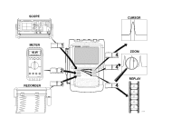
Analyzing Waveforms You can use the analysis functions CURSOR, ZOOM and REPLAY to perform detailed waveform analysis. These functions are described in Chapter 4: "Using Cursors, Zoom and Replay". 1 Using The Scope Analyzing Waveforms 25 - Fluke 199C/S | FE 192,196,199 C Users Manual - Page 34
Fluke 192B - 196B/C - 199B/C Users Manual 26 - Fluke 199C/S | FE 192,196,199 C Users Manual - Page 35
functions of the test tool (hereafter called "meter"). The introduction gives basic examples to show how to use the menus and perform basic operations. Making Meter Connections Use the two 4-mm safety red ( ) and black (COM) banana jack inputs for the Meter functions. (See Figure 12.) Note - Fluke 199C/S | FE 192,196,199 C Users Manual - Page 36
Fluke 192B - 196B/C - 199B/C Users Manual Making Multimeter Measurements The screen displays the numeric readings of the measurements on the meter input. Measuring Resistance Values To measure a resistance, do the following: 1 Connect the red and black test leads from the 4-mm banana jack inputs - Fluke 199C/S | FE 192,196,199 C Users Manual - Page 37
. Scope mode has the advantage of two waveforms being displayed while you perform measurements. Meter mode has the advantage of high measurement resolution. The next example explains a typical current measurement in Meter mode. Warning 3 Carefully read the instructions about the current probe you - Fluke 199C/S | FE 192,196,199 C Users Manual - Page 38
Fluke 192B - 196B/C - 199B/C Users Manual 6 Observe the sensitivity of the current probe. Highlight the corresponding sensitivity in the menu, e.g. 10 mV/A. 7 Accept the current measurement. Now, you will see a screen like in Figure 15 Figure 15. Ampere Measurement Readings 30 - Fluke 199C/S | FE 192,196,199 C Users Manual - Page 39
into memory, see Chapter 6. 2 Using The Multimeter Freezing the Readings Selecting Auto/Manual Ranges To activate manual ranging, do the following during any Meter measurement: 1 Activate manual ranging. 2 Increase or decrease the range. Observe how the bargraph sensitivity changes. Use - Fluke 199C/S | FE 192,196,199 C Users Manual - Page 40
Fluke 192B - 196B/C - 199B/C Users Manual Making Relative Measurements A relative measurement displays the present measurement result relative to a defined reference value. The following example shows how to perform a relative voltage measurement. - Fluke 199C/S | FE 192,196,199 C Users Manual - Page 41
recorder functions of the test tool. The introduction gives examples to show how to use the menus and perform basic operations. Opening the Recorder Main Menu First choose a measurement in scope or meter mode. Now you can choose the recorder functions from the recorder main menu. To open the main - Fluke 199C/S | FE 192,196,199 C Users Manual - Page 42
Fluke 192B - 196B/C - 199B/C Users Manual Plotting Measurements Over Time (TrendPlot™) Use the TrendPlot function to plot a graph of Scope or Meter measurements as function of time. Note Because the navigations for the dual input TrendPlot (Scope) and the single input TrendPlot (Meter) are identical - Fluke 199C/S | FE 192,196,199 C Users Manual - Page 43
Figure 18. TrendPlot Reading When the Scope is in automatic mode, automatic vertical scaling is used to fit the TrendPlot graph on the screen. 5 Set RECORDER to STOP to freeze the recorder - Fluke 199C/S | FE 192,196,199 C Users Manual - Page 44
Fluke 192B - 196B/C - 199B/C Users Manual Changing the Recorder Options At the right bottom of the display you can choose to display the time elapsed from start and the actual time of the day. To change the time reference, proceed from step 6 as follows: 7 Open the Recorder Options menu. - Fluke 199C/S | FE 192,196,199 C Users Manual - Page 45
power-on event of an Uninterruptable Power Supply (UPS). During recording, fast transients are captured. Because of the deep memory, recording can be done for more than one day. This function is similar to the roll mode in many DSO's but has deeper memory and better functionality. Starting a Scope - Fluke 199C/S | FE 192,196,199 C Users Manual - Page 46
Fluke 192B - 196B/C - 199B/C Users Manual Displaying Recorded Data In Normal view, the samples that the Cursors and Zoom functions. See Chapter 4: "Using Replay, Zoom and Cursors". Using Scope Record in Single Sweep Mode Use the recorder Single Sweep function to automatically stop recording when - Fluke 199C/S | FE 192,196,199 C Users Manual - Page 47
Functions Recording Scope Waveforms In Deep Memory (Scope Record) Using External Triggering to Start or Stop Scope Record To record an electrical event that causes a fault, it might be useful to start or stop recording on an external trigger signal: Start on trigger to start recording; recording - Fluke 199C/S | FE 192,196,199 C Users Manual - Page 48
Fluke 192B - 196B/C - 199B/C Users Manual 9 Select one of the Conditions: and jump to Slope:. 10 Select the ". Figure 21. Triggered Single Sweep Recording Analyzing a TrendPlot or Scope Record From a Scope TrendPlot or Scope Record you can use the analysis functions CURSORS and ZOOM to perform - Fluke 199C/S | FE 192,196,199 C Users Manual - Page 49
screen of special interest. • Then zoom in on the signal event. • Finally, make measurements using the cursors. Replaying the 100 Most Recent Scope Screens When you are in scope mode, the test tool automatically stores the 100 most recent screens. When you press the HOLD key or the REPLAY key, the - Fluke 199C/S | FE 192,196,199 C Users Manual - Page 50
Fluke 192B - 196B/C - 199B/C Users Manual Replaying Step-by-Step To step through the last scope screens, do the following: 1 From scope mode, open the on the screen (in this example: SCREEN -84). If the bar is partly white, the memory is not completely filled with 100 screens. From this point - Fluke 199C/S | FE 192,196,199 C Users Manual - Page 51
with the signal event of interest appears. 3 Stop the continuous replay. 4 Using Replay, Zoom and Cursors Replaying the 100 Most Recent Scope Screens Turning Off the Replay Function 4 Turn off REPLAY. Capturing 100 Intermittents Automatically When you use the test tool in triggered mode, 100 - Fluke 199C/S | FE 192,196,199 C Users Manual - Page 52
Fluke 192B - 196B/C - 199B/C Users Manual Zooming in on a Waveform To obtain a more detailed view the time/div) the waveform. 3 Scroll. A position bar displays the position of the zoomed part in relation to the total waveform. Tip Even when the key labels are not displayed at the bottom - Fluke 199C/S | FE 192,196,199 C Users Manual - Page 53
is useful when you quickly need to see the complete waveform and then return to the zoomed part. 4 Display the complete waveform. Press repeatedly to toggle between the zoomed part of the waveform and the complete waveform. 4 Using Replay, Zoom and Cursors Zooming in on a Waveform Turning - Fluke 199C/S | FE 192,196,199 C Users Manual - Page 54
Fluke 192B - 196B/C - 199B/C Users Manual Making Cursor Measurements Cursors allow you to make precise digital on a Waveform To use the cursors for a voltage measurement, do the following: 1 From scope mode, display the cursor key labels. 2 Press to highlight . Observe that two horizontal - Fluke 199C/S | FE 192,196,199 C Users Manual - Page 55
the cursors for a time measurement, or for an RMS measurement of the trace section between the cursors (C versions), do the following: 1 From scope mode, display the cursor key labels. 4 Using Replay, Zoom and Cursors Making Cursor Measurements 2 Press to highlight . Observe that two vertical - Fluke 199C/S | FE 192,196,199 C Users Manual - Page 56
Fluke 192B - 196B/C - 199B/C Users Manual Using Cursors on a A+B, A-B or A*B Waveform Cursor measurements on a A*B waveform give a reading in Watts if input A measures (milli)Volts and input B measures (milli)Amperes. For other - Fluke 199C/S | FE 192,196,199 C Users Manual - Page 57
Measurements To measure rise time, do the following: 1 From scope mode, display the cursor key labels. 2 Press to highlight select the required trace A, B, or M (if a math function is active). 4 Select MANUAL or AUTO (this automatically does steps 5 to 7). 5 Move the upper cursor to 100 - Fluke 199C/S | FE 192,196,199 C Users Manual - Page 58
Fluke 192B - 196B/C - 199B/C Users Manual 50 - Fluke 199C/S | FE 192,196,199 C Users Manual - Page 59
control the trigger level, slope, and trigger delay for a better view of the signal. (See next section.) • For dedicated applications, use one of the four manual trigger functions: • Edge triggering • External triggering • Video triggering • Pulse Width triggering 51 - Fluke 199C/S | FE 192,196,199 C Users Manual - Page 60
Fluke 192B - 196B/C - 199B/C Users Manual Setting Trigger Level and Slope The Connect-and-View™ function enables hands-off triggering to display complex unknown signals. When your test tool is in manual range, do the following: Perform an auto set. AUTO appears at the top right of the screen. - Fluke 199C/S | FE 192,196,199 C Users Manual - Page 61
Using Trigger Delay or Pre-trigger You can begin to display the waveform some time before or after the trigger point has been detected. Initially, you have 2 divisions of pre-trigger view (negative delay). To set the trigger delay, do the following: 5 Hold down to adjust the trigger delay. - Fluke 199C/S | FE 192,196,199 C Users Manual - Page 62
Fluke 192B - 196B/C - 199B/C Users Manual Automatic Trigger Options In the trigger menu, settings for automatic However, when you measure frequencies lower than 15 Hz, the test tool must be instructed to analyze low frequency components for automatic triggering: 4 Select > 1 HZ and return - Fluke 199C/S | FE 192,196,199 C Users Manual - Page 63
signal is instable or has a very low frequency, use edge triggering to obtain full manual trigger control. To trigger on rising edges of the input A waveform, do the following the key labels at the bottom of the screen have adapted to allow further selection of specific edge trigger settings: 55 - Fluke 199C/S | FE 192,196,199 C Users Manual - Page 64
Fluke 192B - 196B/C - 199B/C Users Manual Triggering on Noisy Waveforms To reduce jitter on the screen when triggering on noisy waveforms, you can use a noise rejection filter. Continue from step 3 of - Fluke 199C/S | FE 192,196,199 C Users Manual - Page 65
Figure 30. 6 Set NCycle to On Observe that the key labels at the bottom of the screen have been changed to allow further selection of specific N-Cycle trigger settings: Figure 30. N-Cycle triggering 57 - Fluke 199C/S | FE 192,196,199 C Users Manual - Page 66
Fluke 192B - 196B/C - 199B/C Users Manual Triggering on External Waveforms Use external triggering when you want to display waveforms on inputs A and B while triggering on a third signal. You can choose external triggering with automatic triggering or with edge triggering. 1 Supply been adapted to - Fluke 199C/S | FE 192,196,199 C Users Manual - Page 67
level and slope are now fixed. Observe that the key labels at the bottom of the screen have been changed to allow further selection of specific video trigger settings: 5 Select positive signal polarity for video signals with negative going sync pulses. 59 - Fluke 199C/S | FE 192,196,199 C Users Manual - Page 68
Fluke 192B - 196B/C - 199B/C Users Manual Triggering on Video Frames Use FIELD 1 or FIELD 2 to trigger either on the first half of the frame (odd) or on the second half of the frame (even).To trigger on the second half of the frame, do the following: 7 Choose FIELD 2. The signal part of the even - Fluke 199C/S | FE 192,196,199 C Users Manual - Page 69
Triggering on Pulses Use pulse width triggering to isolate and display specific pulses that you can qualify by time, such as glitches, missing pulses, bursts or signal dropouts. only. Observe that the trigger key labels at the bottom of the screen have been adapted to set the pulse conditions: 61 - Fluke 199C/S | FE 192,196,199 C Users Manual - Page 70
Fluke 192B - 196B/C - 199B/C Users Manual To set the pulse width to 5 ms, do the following: 7 Enable the arrow keys to adjust the pulse width. 8 Select 5 ms. All narrow positive pulses - Fluke 199C/S | FE 192,196,199 C Users Manual - Page 71
Trigger. The test tool is now prepared to trigger on pulse gaps. Observe that the trigger menu at the bottom of the screen has been adapted to set the pulse condition: 3 Select Pulse Width on A... to open the Trigger on Pulse Width menu. 63 - Fluke 199C/S | FE 192,196,199 C Users Manual - Page 72
Fluke 192B - 196B/C - 199B/C Users Manual To set the pulse width to 150 ms, continue as follows: 7 Enable the arrow keys to adjust the pulse width. 8 Select 150 ms. Figure 34. Triggering on Missing Pulses 64 - Fluke 199C/S | FE 192,196,199 C Users Manual - Page 73
introduction to the general functions of the test tool that can be used in the three main modes: Scope, Meter, or Recorder. You will find information on printer and computer communication at the end of date. • Recall a setup to continue a measurement with the recalled operating configuration. 65 - Fluke 199C/S | FE 192,196,199 C Users Manual - Page 74
Fluke 192B - 196B/C - 199B/C Users Manual Saving Screens with Associated Setups To save a screen in memory more than what is just visible on the screen. In TrendPlot or scope record mode the full recording is saved. In scope mode you can save all 100 replay screens in a single record+setup memory - Fluke 199C/S | FE 192,196,199 C Users Manual - Page 75
Deleting Screens with Associated Setups To delete all screens and associated setups, continue from step 2 of the previous example as follows: 3 Delete all saved screens and setups. To delete only one screen and setup, continue from step 2 of the previous example as follows: 3 Highlight SCREEN+ - Fluke 199C/S | FE 192,196,199 C Users Manual - Page 76
Fluke 192B - 196B/C - 199B/C Users Manual 4 Use RECALL FOR REFERENCE to recall the saved screen. 5 Resume the measurement. Both, the reference screen and the measurement that RUN appears at the top right of the screen. From this point you continue in the new operating configuration. 68 - Fluke 199C/S | FE 192,196,199 C Users Manual - Page 77
a printer. Connecting to a Computer To connect the test tool to a PC or notebook computer and use the FlukeView software for Windows® (SW90W), do the following: z Use the Optically Isolated Adapter/Cable (USB: OC4USB; RS-232: PM9080) to connect a computer to the OPTICAL PORT of the test tool. (See - Fluke 199C/S | FE 192,196,199 C Users Manual - Page 78
Fluke 192B - 196B/C - 199B/C Users Manual Note For information about installing and using the FlukeView ScopeMeter software, see the SW90W Users Manual. A Software & Cable Carrying Case Kit is optionally available as model number SCC190. Connecting to a Printer To print a screen directly to a - Fluke 199C/S | FE 192,196,199 C Users Manual - Page 79
rate: 1 Display the USER OPTIONS key labels. 2 Open the User Options menu. 3 Open . Consult the manual that came with thermal printer you must use the printer adapter cable PAC91. (See page 70.) 2 Display the SAVE/PRINT key labels. 3 Start printing. A message appears at the bottom of - Fluke 199C/S | FE 192,196,199 C Users Manual - Page 80
Fluke 192B - 196B/C - 199B/C Users Manual 72 - Fluke 199C/S | FE 192,196,199 C Users Manual - Page 81
Chapter 7 Tips About this Chapter This chapter gives you information and tips on how you can make the best use of the test tool. Using the Standard Accessories The following illustrations show the use of the standard accessories such as voltage probes, test leads, and the various clips. 73 - Fluke 199C/S | FE 192,196,199 C Users Manual - Page 82
Fluke 192B - 196B/C - 199B/C Users Manual Figure 38. HF Voltage Probe Connection Using Ground Spring Warning To avoid electrical shock or fire, do not connect the ground spring to voltages higher than 30 Vrms from earth ground. Figure 40. Electronic Connections for Scope Measurements Using Hook - Fluke 199C/S | FE 192,196,199 C Users Manual - Page 83
Using the Independently Floating Isolated Inputs You can use the independently floating isolated inputs to measure signals that are independently floating from each other. Independently floating isolated inputs offer additional safety and measurement capabilities compared to inputs with common - Fluke 199C/S | FE 192,196,199 C Users Manual - Page 84
Fluke 192B - 196B/C - 199B/C Users Manual ANALOG INPUT DIGITAL CONTROLLER ANALOG GROUND DIGITAL GROUND Figure 42. Parasitic capacitance between probes, instrument and environment MOTION/MOTOR CONTROLLER DC BUS + DIGITAL GROUND M - DC BUS Figure 43. Parasitic capacitance between analog and - Fluke 199C/S | FE 192,196,199 C Users Manual - Page 85
key label at any time: Hide any key label or menu. To display menus or key labels, press one of the yellow menu keys, e.g. the SCOPE key. 77 - Fluke 199C/S | FE 192,196,199 C Users Manual - Page 86
Fluke 192B - 196B/C - 199B/C Users Manual Changing the Information Language During operation of the test tool, messages may appear at the bottom of the screen. You can select the language in which these messages are displayed. In - Fluke 199C/S | FE 192,196,199 C Users Manual - Page 87
date and time clock. For example, to change the date to 19 April, 2002, do the following: 1 Display the USER key labels. 2 Open the User Options menu. 2 Open the User Options menu. 3 Open Display Options menu. 3 Open Date Adjust menu. 4 Choose display mode Color or 4 Choose 2002, jump - Fluke 199C/S | FE 192,196,199 C Users Manual - Page 88
Fluke 192B - 196B/C - 199B/C Users Manual 6 Choose 19, jump to Format. 7 Choose DD/MM/YY, accept the new date. You can change the time in a similar way by opening the Time Adjust menu (steps 2 and 3.) Saving Battery Life When operated on the battery (no battery charger connected), the test - Fluke 199C/S | FE 192,196,199 C Users Manual - Page 89
key labels. 2 Open the User Options menu. 3 Open the Auto Set Adjust menu. If the frequency range is set to > 15 Hz, the Connect-andView function responds more quickly. The response is quicker because the test tool is instructed not to analyze low frequency signal components. However, when you - Fluke 199C/S | FE 192,196,199 C Users Manual - Page 90
Fluke 192B - 196B/C - 199B/C Users Manual 82 - Fluke 199C/S | FE 192,196,199 C Users Manual - Page 91
by the user. For complete service, disassembly, repair, and calibration information, see the Service Manual. You will find the part number of the Service Manual in the section "Parts and Accessories" extended period of time, charge the NiMH (Nickel-Metal Hydride) batteries before storing. 83 - Fluke 199C/S | FE 192,196,199 C Users Manual - Page 92
Fluke 192B - 196B/C - 199B/C Users Manual Charging the Batteries At delivery, the NiMH batteries may be empty and must be charged for 4 hours (with the test tool turned off) to reach full charge. When fully charged, the batteries provide 4 hours of use. When battery power is used, the battery - Fluke 199C/S | FE 192,196,199 C Users Manual - Page 93
Test Tool Extending Battery Operation Time To refresh the battery, make sure that the test tool is line powered and proceed as follows: 1 Display the USER key labels. 2 Open the User Options menu. A message appears asking whether you want to start the refresh cycle now. 3 Start the refresh - Fluke 199C/S | FE 192,196,199 C Users Manual - Page 94
it should not be necessary to replace the battery pack. However, if replacement is needed, this should be done by qualified personnel only. Contact your nearest Fluke center for more information. Calibrating the Voltage Probes To meet full user specifications, you need to adjust the red and gray - Fluke 199C/S | FE 192,196,199 C Users Manual - Page 95
the 10:1 probe calibration. 6 Start the probe calibration. A message appears telling you how to connect the probe. Connect the red 10:1 voltage probe from the red input A jack to the red banana jack. Connect the reference lead to the black banana jack. (See Figure 48.) 7 Adjust the trimmer - Fluke 199C/S | FE 192,196,199 C Users Manual - Page 96
Fluke 192B - 196B/C - 199B/C Users Manual Displaying Calibration Information You can display version number and calibration date: 1 Display the USER key labels. 2 Open the Version & Calibration menu. Parts and Accessories The following tables list the user-replaceable parts for the various - Fluke 199C/S | FE 192,196,199 C Users Manual - Page 97
North America. The 230 V rating of the BC190/808 is not for use in North America. For other countries, a line plug adapter complying with the applicable National Requirements must be used. Voltage Probe Set (Red), designed for use with the Fluke ScopeMeter 190 series test tool. The set includes the - Fluke 199C/S | FE 192,196,199 C Users Manual - Page 98
199B/C Users Manual Item Voltage Probe Set (Gray), designed for use with the Fluke ScopeMeter 190 series test tool. The set includes the following items (not available separately): • 10:1 Voltage Probe (gray) • 4-mm Test Probe for Probe Tip (gray) • Hook Clip for Probe Tip (gray) • Ground Lead with - Fluke 199C/S | FE 192,196,199 C Users Manual - Page 99
Lead with Mini Alligator Clip (black) • 5x Ground Spring for Probe Tip (black) Table 2. Users Manuals Item Getting Started Manual (English) Getting Started Manual (German) Getting Started Manual (French) Getting Started Manual (Spanish) Getting Started Manual (Portuguese) Getting Started Manual - Fluke 199C/S | FE 192,196,199 C Users Manual - Page 100
Fluke 192B - 196B/C - 199B/C Users Manual Optional Accessories Item Software & Cable Carrying Case Kit Set contains the following parts: Optically Isolated USB Adapter/Cable Hard Carrying Case FlukeView® ScopeMeter® Software for Windows® Optically Isolated USB Adapter/Cable Optically Isolated RS-232 - Fluke 199C/S | FE 192,196,199 C Users Manual - Page 101
Troubleshooting The Test Tool Does Not Start Up • The batteries may be completely empty. In this case the test tool will not start up, even if it is powered by the battery charger. Charge the batteries first: power the test tool with the battery charger without turning it on. Wait about 15 minutes - Fluke 199C/S | FE 192,196,199 C Users Manual - Page 102
Fluke 192B - 196B/C - 199B/C Users Manual FlukeView Does Not Recognize The Test Tool • Make sure the interface cable to another COM port. Battery Operated Fluke Accessories Do Not Function • When using battery operated Fluke accessories, always first check the battery condition of the accessory with - Fluke 199C/S | FE 192,196,199 C Users Manual - Page 103
(including approval) Safety Requirements for Electrical Equipment for Measurement, Control, and Laboratory Use. This manual contains information and warnings that must be followed by the user to ensure safe operation and to keep the instrument in a safe condition. Use of this equipment in a manner - Fluke 199C/S | FE 192,196,199 C Users Manual - Page 104
Fluke 192B - 196B/C - 199B/C Users Manual Dual Input Oscilloscope Isolated Inputs A and B (Vertical) Bandwidth, DC Coupled FLUKE 199B/C 200 MHz (-3 dB) FLUKE 196B/C 100 MHz (-3 dB) FLUKE 192B 60 MHz (-3 dB) Lower Frequency Limit, AC Coupled with 10:1 probe 2 Hz (-3 dB) direct (1:1 5 Hz (-3 dB) - Fluke 199C/S | FE 192,196,199 C Users Manual - Page 105
Positive, Negative, Dual (C versions) 9 Specifications Dual Input Oscilloscope Edge Trigger Screen Update Free Run, On FLUKE 199B/C 1 division 250 MHz (FLUKE 199B/C 2 divisions 100 MHz (FLUKE 196B/C 1 division 150 MHz (FLUKE 196B/C 2 divisions 60 MHz (FLUKE 192B 1 division 100 MHz (FLUKE - Fluke 199C/S | FE 192,196,199 C Users Manual - Page 106
Fluke 192B - 196B/C - 199B/C Users Manual Pulse Width Trigger Screen Update On Trigger, Single Shot Trigger Conditions T, >T, =T (±10 %), ≠T(±10 %) Source A Polarity Positive or negative pulse Pulse Time Adjustment Range .......... 0.01 div. - Fluke 199C/S | FE 192,196,199 C Users Manual - Page 107
+ 10 counts) 60 Hz direct (1:1 1.9 % + 10 counts) With the 10:1 probe the low frequency roll off point will be lowered to 2 Hz, which improves the AC 's frequency roll off starts affecting accuracy. Normal Mode DC Rejection 50 dB 9 Specifications Automatic Scope Measurements All accuracies are - Fluke 199C/S | FE 192,196,199 C Users Manual - Page 108
Fluke 192B - 196B/C - 199B/C Users Manual Amperes (AMP) With Optional Current Probe or Current Shunt Ranges same as VDC, VAC, VAC+DC Probe Sensitivity 100 µV/A, 1 mV/A, 10 mV/A, 100 mV/A, 1 V/A, 10 V/A, and 100 V/A Accuracy same as VDC, VAC, VAC+DC (add current probe or current shunt accuracy) - Fluke 199C/S | FE 192,196,199 C Users Manual - Page 109
Power Power Factor ratio between Watts and VA Range 0.00 to 1.00 Watt degree Accuracy 0.1 Hz to 1 MHz 2 degrees 1 MHz to 10 MHz 3 degrees 9 Specifications Automatic Scope Measurements Temperature (TEMP) With Optional Temperature Probe Ranges (°C or °F 40.0 to +100.0 ° -100 to +250 ° -100 to - Fluke 199C/S | FE 192,196,199 C Users Manual - Page 110
Fluke 192B - 196B/C - 199B/C Users Manual Meter Meter Input Input Coupling DC Frequency Response DC to 10 kHz (-3 dB) Input Impedance 1 MΩ (±1 %)//10 pF (±1.5 pF) Max. Input Voltage 1000 V CAT II 600 V CAT III (For detailed specifications, see "Safety") Meter Functions Ranging Auto, Manual - Fluke 199C/S | FE 192,196,199 C Users Manual - Page 111
.0 ° -100 to +1000 ° -100 to + 2500 ° Probe Sensitivity 1 mV/°C and 1 mV/°F DC Voltage (VDC) Ranges Hz ±1 % .... >60 dB 9 Specifications DMM Measurements on Meter Inputs AC Voltage (VAC frequencies the frequency roll off of the Meter input starts affecting accuracy. Normal Mode DC Rejection 50 dB - Fluke 199C/S | FE 192,196,199 C Users Manual - Page 112
Fluke 192B - 196B/C - 199B/C Users Manual Amperes (AMP) With Optional Current Probe or Current Shunt Ranges same as VDC, VAC, VAC+DC Probe Sensitivity 100 µV/A, 1 mV/A, 10 mV/A, 100 mV/A, 1 V/A, 10 V/A, and 100 V/A Accuracy same as VDC, VAC, VAC+DC (add current probe or current shunt accuracy) - Fluke 199C/S | FE 192,196,199 C Users Manual - Page 113
/m2 (B-versions) Power Rechargeable NiMH Batteries: Operating Time 4 hours Charging Time 4 hours Allowable ambient temperature during charging: .....0 to 40 °C (32 to 104 °F) Auto power down time (battery saving 5 min, 30 min or disabled Battery Charger / Power Adapter BC190: • BC190/801 European - Fluke 199C/S | FE 192,196,199 C Users Manual - Page 114
Fluke 192B - 196B/C - 199B/C Users Manual Probe Calibration Manual pulse adjustment and automatic DC adjustment with probe check. Generator Output 3 Vpp / 500 Hz square wave Memory Number of Scope Memories 10 Each memory can contain two waveforms plus corresponding setups Number of Recorder - Fluke 199C/S | FE 192,196,199 C Users Manual - Page 115
Operating: battery only 0 to 50 °C (32 to 122 °F) power adapter 0 to 40 °C (32 to 104 °F) Storage 20 to +60 °C (-4 to +140 °F) Humidity Operating: Voltages Input A and B directly 300 V CAT III Input A and B via 10:1 probe 1000 V CAT II 600 V CAT III METER/EXT TRIG inputs 1000 V CAT II - Fluke 199C/S | FE 192,196,199 C Users Manual - Page 116
Fluke 192B - 196B/C - 199B/C Users Manual } VOLTAGE (Vrms) 30 Figure 49. Max. Input Voltage vs. Frequency FREQUENCY (kHz) Figure 50. Safe Handling: Max. Voltage Between Scope References, Between Scope References and Meter Reference, and Between Scope References/Meter Reference and earth ground. - Fluke 199C/S | FE 192,196,199 C Users Manual - Page 117
(with FLUKE 199C) .....DC to 200 MHz (-3 dB) Accuracy Probe accuracy when adjusted on the test tool: DC to 20 kHz 1 % 20 kHz to 1 MHz 2 % 1 MHz to 25 MHz 3 % For higher frequencies the probe's roll off starts affecting the accuracy 9 Specifications 10:1 Probe Environmental Temperature Operating - Fluke 199C/S | FE 192,196,199 C Users Manual - Page 118
Users Manual Electromagnetic Immunity The Fluke 190 series, including standard accessories, conforms with the EEC directive 89/336 for EMC immunity, as defined by EN-61326-1, with the addition of the following tables. Scope Mode (10 ms/div): Trace disturbance with VPS200 voltage probe test leads - Fluke 199C/S | FE 192,196,199 C Users Manual - Page 119
Automatic Power Shutdown, 80 Automatic Scope Measurements, 13 Automatic Triggering, 54 Average, 15 -B- Banana Jack Inputs, 10, 27, 34 Bandwidth, 96, 102 Bargraph, 28 Battery Charger, 3, 89 Charging, 2, 84 Indicator, 84 Life, 80 Refresh, 85 Refresh Date, 88 Replacing, 86 BC190 Battery Charger, 3, 89 - Fluke 199C/S | FE 192,196,199 C Users Manual - Page 120
Fluke 192B - 196B/C - 199B/C Users Manual Connecting A Printer, 70 Connections, 10, 27 Continuity, 102 Contrast, 78 CS20MA Current Shunt, 92 Current Measurement, 29 Current Probe , 107 Electronic Scope Connections, 74 Emission Leads, 3, 89 Ground Spring, 3, 89 -H- Hard Case, 3, 92 HF Voltage Probe - Fluke 199C/S | FE 192,196,199 C Users Manual - Page 121
a Menu, 9 N-Cycle Triggering, 57 NiMH Battery, 84 NiMH Battery, 83 Noisy Waveforms, 20, 56 -O- Ohm (Ω), 102 Operating Time, 105 Optical Interface, 69, 70, 106 Oscilloscope, 96 OVERVIEW, 45 -P- PAC91, 70, 92 Parallel Print Cable, 92 Parallel Printer, 70 Parts, 88 Pass - Fail Testing, 24 Peak - Fluke 199C/S | FE 192,196,199 C Users Manual - Page 122
Fluke 192B - 196B/C - 199B/C Users Manual Scope Record, 104 Scope Record, 37 Screen Contrast, 78 Screen Without Menus, 10, 77 Serial Printer, 70 Service Manual, 92 Shock, 107 Single Shot, 56 Single Sweep Mode, 38 Slope, 52, 97 Slow Variations, 34 Smooth, 15 Soft Case, 92 Software, 3, 92 Software
-
 1
1 -
 2
2 -
 3
3 -
 4
4 -
 5
5 -
 6
6 -
 7
7 -
8
-
9
-
10
-
11
-
12
-
13
-
14
-
15
-
16
-
17
-
18
-
19
-
20
-
21
-
22
-
23
-
24
-
25
-
26
-
27
-
28
-
29
-
30
-
31
-
32
-
33
-
34
-
35
-
36
-
37
-
38
-
39
-
40
-
41
-
42
-
43
-
44
-
45
-
46
-
47
-
48
-
49
-
50
-
51
-
52
-
53
-
54
-
55
-
56
-
57
-
58
-
59
-
60
-
61
-
62
-
63
-
64
-
65
-
66
-
67
-
68
-
69
-
70
-
71
-
72
-
73
-
74
-
75
-
76
-
77
-
78
-
79
-
80
-
81
-
82
-
83
-
84
-
85
-
86
-
87
-
88
-
89
-
90
-
91
-
92
-
93
-
94
-
95
-
96
-
97
-
98
-
99
-
100
-
101
-
102
-
103
-
104
-
105
-
106
-
107
-
108
-
109
-
110
-
111
-
112
-
113
-
114
-
115
-
116
-
117
-
118
-
119
-
120
-
121
-
122
 |
 |

4822 872 30601
October 2002 Rev. 2, 12/04
© 2002 Fluke Corporation. All rights reserved. Printed in the Netherlands.
All product names are trademarks of their respective companies.
Fluke 192B - 196B/C - 199B/C
ScopeMeter
Users Manual