Fluke 199C/S FE 192,196,199 C Users Manual - Page 60
Setting Trigger Level and Slope, Screen with all Trigger Information
 |
View all Fluke 199C/S manuals
Add to My Manuals
Save this manual to your list of manuals |
Page 60 highlights
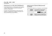
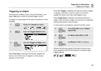
Fluke 192B - 196B/C - 199B/C Users Manual Setting Trigger Level and Slope The Connect-and-View™ function enables hands-off triggering to display complex unknown signals. When your test tool is in manual range, do the following: Perform an auto set. AUTO appears at the top right of the screen. Automatic triggering assures a stable display of virtually any signal. From this point, you can take over the basic trigger controls such as level, slope and delay. To optimize trigger level and slope manually, do the following: 1 Display the TRIGGER key labels. 2 Trigger on either positive slope or negative slope of the chosen waveform. Dual Slope Triggering ( X ): C versions can trigger on both positive slope and negative slope. 52 3 Enable the arrow keys for manual trigger level adjustment. Figure 27. Screen with all Trigger Information 4 Adjust the trigger level. Observe the trigger icon that indicates the trigger position, trigger level, and slope. At the bottom of the screen the trigger parameters are displayed (See Figure 27) . For example, means that input A is used as the trigger source with a positive slope. When no trigger is found, the trigger parameters appear in gray.
-
 1
1 -
2
-
3
-
4
-
5
-
6
-
7
-
8
-
9
-
10
-
11
-
12
-
13
-
14
-
15
-
16
-
17
-
18
-
19
-
20
-
21
-
22
-
23
-
24
-
25
-
26
-
27
-
28
-
29
-
30
-
31
-
32
-
33
-
34
-
35
-
36
-
37
-
38
-
39
-
40
-
41
-
42
-
43
-
44
-
45
-
46
-
47
-
48
-
49
-
50
-
51
-
52
-
53
-
54
-
 55
55 -
 56
56 -
 57
57 -
 58
58 -
 59
59 -
 60
60 -
 61
61 -
 62
62 -
 63
63 -
 64
64 -
 65
65 -
66
-
67
-
68
-
69
-
70
-
71
-
72
-
73
-
74
-
75
-
76
-
77
-
78
-
79
-
80
-
81
-
82
-
83
-
84
-
85
-
86
-
87
-
88
-
89
-
90
-
91
-
92
-
93
-
94
-
95
-
96
-
97
-
98
-
99
-
100
-
101
-
102
-
103
-
104
-
105
-
106
-
107
-
108
-
109
-
110
-
111
-
112
-
113
-
114
-
115
-
116
-
117
-
118
-
119
-
120
-
121
-
122
 |
 |