Fluke 199C/S FE 192,196,199 C Users Manual - Page 19
Making Scope Connections, Scope Connections
 |
View all Fluke 199C/S manuals
Add to My Manuals
Save this manual to your list of manuals |
Page 19 highlights
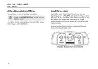
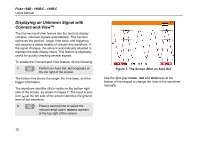
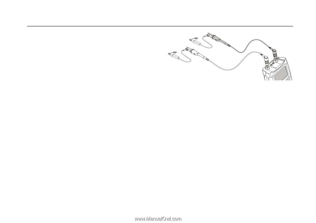
Making Scope Connections To make dual input scope measurements, connect the red voltage probe to input A, and the gray voltage probe to input B. Connect the short ground leads of each voltage probe to its own reference potential. (See Figure 6.) Note To maximally benefit from having independently isolated floating inputs and to avoid problems caused by improper use, read Chapter 7: "Tips". 1 Using The Scope Making Scope Connections Figure 6. Scope Connections 11
-
 1
1 -
2
-
3
-
4
-
5
-
6
-
7
-
8
-
9
-
10
-
11
-
12
-
13
-
 14
14 -
 15
15 -
 16
16 -
 17
17 -
 18
18 -
 19
19 -
 20
20 -
 21
21 -
 22
22 -
 23
23 -
 24
24 -
25
-
26
-
27
-
28
-
29
-
30
-
31
-
32
-
33
-
34
-
35
-
36
-
37
-
38
-
39
-
40
-
41
-
42
-
43
-
44
-
45
-
46
-
47
-
48
-
49
-
50
-
51
-
52
-
53
-
54
-
55
-
56
-
57
-
58
-
59
-
60
-
61
-
62
-
63
-
64
-
65
-
66
-
67
-
68
-
69
-
70
-
71
-
72
-
73
-
74
-
75
-
76
-
77
-
78
-
79
-
80
-
81
-
82
-
83
-
84
-
85
-
86
-
87
-
88
-
89
-
90
-
91
-
92
-
93
-
94
-
95
-
96
-
97
-
98
-
99
-
100
-
101
-
102
-
103
-
104
-
105
-
106
-
107
-
108
-
109
-
110
-
111
-
112
-
113
-
114
-
115
-
116
-
117
-
118
-
119
-
120
-
121
-
122
 |
 |
Using The Scope
Making Scope Connections
1
11
Making Scope Connections
To make dual input scope measurements, connect the red
voltage probe to input A, and the gray voltage probe to
input B. Connect the short ground leads of
each
voltage
probe to its
own
reference potential. (See Figure 6.)
Note
To maximally benefit from having independently
isolated floating inputs and to avoid problems
caused by improper use, read Chapter 7: “Tips”.
Figure 6. Scope Connections