Fluke 199C/S FE 192,196,199 C Users Manual - Page 83
Using the Independently Floating, Isolated Inputs, Measuring Using Independently Floating Isolated
 |
View all Fluke 199C/S manuals
Add to My Manuals
Save this manual to your list of manuals |
Page 83 highlights
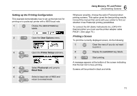
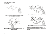
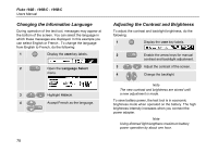
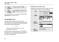
Using the Independently Floating Isolated Inputs You can use the independently floating isolated inputs to measure signals that are independently floating from each other. Independently floating isolated inputs offer additional safety and measurement capabilities compared to inputs with common references or grounds. Measuring Using Independently Floating Isolated Inputs The test tool has independently floating isolated inputs. Each input section (A, B, External Trigger / DMM) has its own signal input and its own reference input. The reference input of each input section is electrically isolated from the reference inputs of the other input sections. The isolated input architecture makes the test tool about as versatile as having three independent instruments. The advantages of having independently floating isolated inputs are: • It allows simultaneous measurement of independently floating signals. 7 Tips Using the Independently Floating Isolated Inputs • Additional safety. Since the commons are not directly connected, the chance of causing short circuit when measuring multiple signals is greatly reduced. • Additional safety. When measuring in systems with multiple grounds, the ground currents induced are kept to a minimum. Because the references are not connected together inside the test tool, each reference of the used inputs must be connected to a reference voltage. Independently floating isolated inputs are still coupled by parasitic capacitance. This can occur between the input references and the environment, and between the input references mutually (see Figure 42). For this reason, you should connect the references to a system ground or another stable voltage. If the reference of an input is connected to a high speed and / or high voltage signal, you should be aware of parasitic capacitance. (See Figure 42 , Figure 43, Figure 44 and Figure 45.) 75
-
 1
1 -
2
-
3
-
4
-
5
-
6
-
7
-
8
-
9
-
10
-
11
-
12
-
13
-
14
-
15
-
16
-
17
-
18
-
19
-
20
-
21
-
22
-
23
-
24
-
25
-
26
-
27
-
28
-
29
-
30
-
31
-
32
-
33
-
34
-
35
-
36
-
37
-
38
-
39
-
40
-
41
-
42
-
43
-
44
-
45
-
46
-
47
-
48
-
49
-
50
-
51
-
52
-
53
-
54
-
55
-
56
-
57
-
58
-
59
-
60
-
61
-
62
-
63
-
64
-
65
-
66
-
67
-
68
-
69
-
70
-
71
-
72
-
73
-
74
-
75
-
76
-
77
-
 78
78 -
 79
79 -
 80
80 -
 81
81 -
 82
82 -
 83
83 -
 84
84 -
 85
85 -
 86
86 -
 87
87 -
 88
88 -
89
-
90
-
91
-
92
-
93
-
94
-
95
-
96
-
97
-
98
-
99
-
100
-
101
-
102
-
103
-
104
-
105
-
106
-
107
-
108
-
109
-
110
-
111
-
112
-
113
-
114
-
115
-
116
-
117
-
118
-
119
-
120
-
121
-
122
 |
 |