Fluke 199C/S FE 192,196,199 C Users Manual - Page 106
Automatic Scope Measurements, Pulse Width Trigger, Continuous Auto Set
 |
View all Fluke 199C/S manuals
Add to My Manuals
Save this manual to your list of manuals |
Page 106 highlights
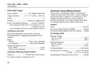
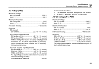
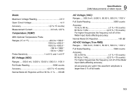
Fluke 192B - 196B/C - 199B/C Users Manual Pulse Width Trigger Screen Update On Trigger, Single Shot Trigger Conditions T, >T, =T (±10 %), ≠T(±10 %) Source A Polarity Positive or negative pulse Pulse Time Adjustment Range .......... 0.01 div. to 655 div. with a minimum of 300 ns (T) or 500 ns (=T, ≠T), a maximum of 10 s, and a resolution of 0.01 div. with a minimum of 50 ns Continuous Auto Set Autoranging attenuators and time base, automatic Connect-and-View™ triggering with automatic source selection. Modes Normal 15 Hz to max. bandwidth Low Frequency 1 Hz to max. bandwidth Minimum Amplitude A and B DC to 1 MHz 10 mV 1 MHz to max. bandwidth 20 mV Automatic Capturing Scope Screens Capacity 100 dual input scope Screens For viewing screens, see Replay function. 98 Automatic Scope Measurements The accuracy of all readings is within ± (% of reading + number of counts) from 18 °C to 28 °C. Add 0.1x (specific accuracy) for each °C below 18 °C or above 28 °C. For voltage measurements with 10:1 probe, add probe accuracy, see section '10:1 Probe' on page 109. At least 1.5 waveform period must be visible on the screen. General Inputs A and B DC Common Mode Rejection (CMRR 100 dB AC Common Mode Rejection at 50, 60, or 400 Hz ......>60 dB DC Voltage (VDC) Maximum Voltage with 10:1 probe 1000 V direct (1:1 300 V Maximum Resolution with 10:1 probe 1 mV direct (1:1 100 µV Full Scale Reading 1100 counts Accuracy at 5 s to 5 µs/div 1.5 % +5 counts) 2 mV/div...... ±(1.5 % + 10 counts) Normal Mode AC Rejection at 50 or 60 Hz 60 dB
-
 1
1 -
2
-
3
-
4
-
5
-
6
-
7
-
8
-
9
-
10
-
11
-
12
-
13
-
14
-
15
-
16
-
17
-
18
-
19
-
20
-
21
-
22
-
23
-
24
-
25
-
26
-
27
-
28
-
29
-
30
-
31
-
32
-
33
-
34
-
35
-
36
-
37
-
38
-
39
-
40
-
41
-
42
-
43
-
44
-
45
-
46
-
47
-
48
-
49
-
50
-
51
-
52
-
53
-
54
-
55
-
56
-
57
-
58
-
59
-
60
-
61
-
62
-
63
-
64
-
65
-
66
-
67
-
68
-
69
-
70
-
71
-
72
-
73
-
74
-
75
-
76
-
77
-
78
-
79
-
80
-
81
-
82
-
83
-
84
-
85
-
86
-
87
-
88
-
89
-
90
-
91
-
92
-
93
-
94
-
95
-
96
-
97
-
98
-
99
-
100
-
 101
101 -
 102
102 -
 103
103 -
 104
104 -
 105
105 -
 106
106 -
 107
107 -
 108
108 -
 109
109 -
 110
110 -
 111
111 -
112
-
113
-
114
-
115
-
116
-
117
-
118
-
119
-
120
-
121
-
122
 |
 |