Sony DPP-FP90 Instruction Manual - Page 7
Printer rear panel, Printer left side panel, Handle, Ventilation holes, DC IN 24V jack - paper tray
 |
View all Sony DPP-FP90 manuals
Add to My Manuals
Save this manual to your list of manuals |
Page 7 highlights
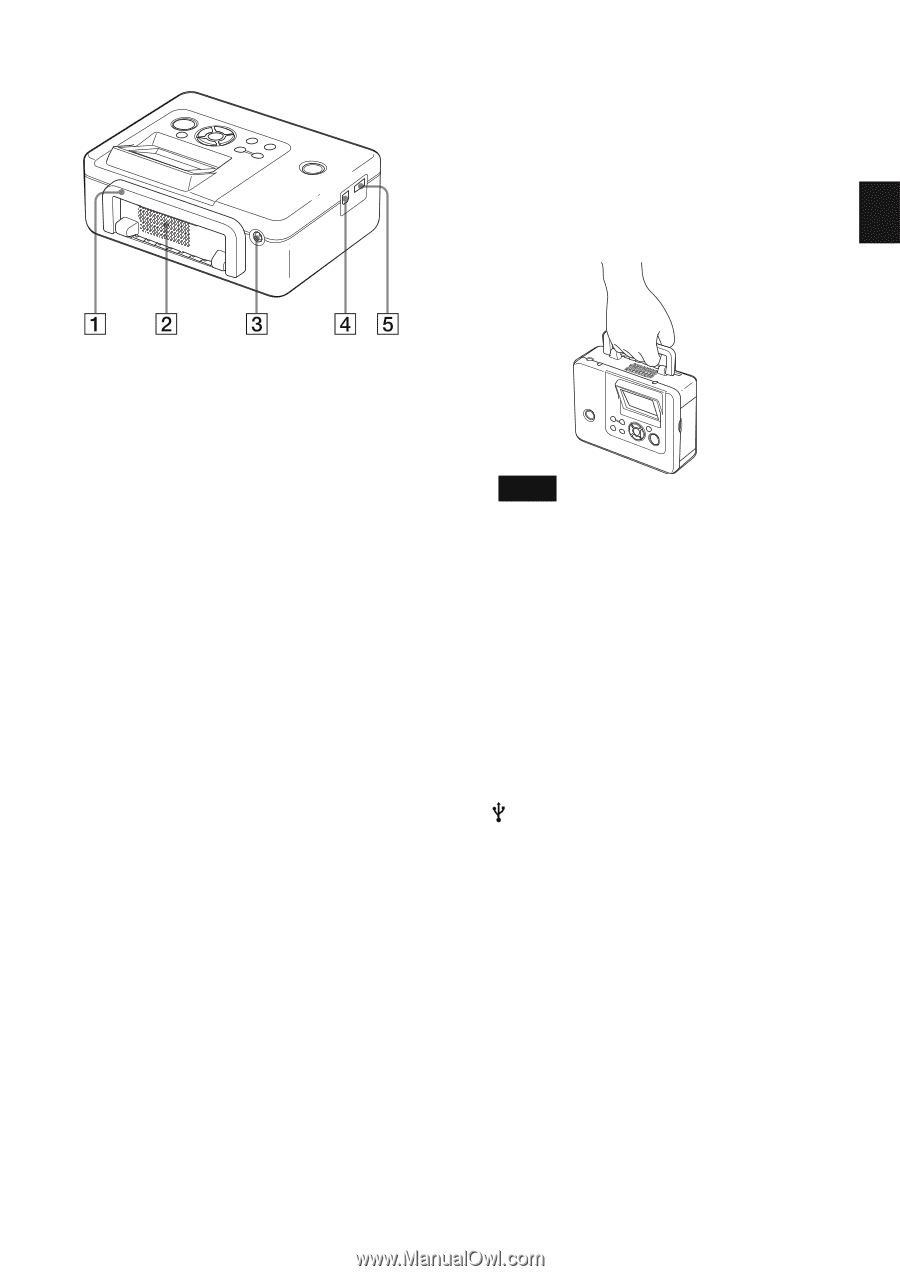
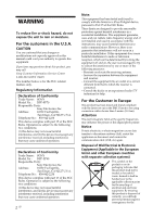
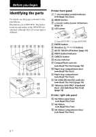
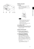
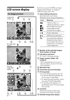
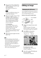
Before you begin Printer rear panel 1 Handle As illustrated below, raise the handle when you bring the printer. When you use the printer, close it to its original position. Notes • When you bring the printer, make sure to remove memory cards, external device, and paper tray. Otherwise malfunctions may occur. • When using the DPP-FP90, set the LCD panel to its original position. 2 Ventilation holes 3 DC IN 24V jack (.Read This First) Connect the supplied AC power adaptor into this connector. Printer left side panel 4 USB connector (page 41) When using the printer in PC mode, connect a PC into this connector. 5 PictBridge/EXT INTERFACE connector (pages 35 to 38) When using a PictBridge-compliant digital camera, a mass-storage device such as a USB memory or photo storage, Bluetooth USB adaptor (DPPA-BT1*), or other external USB device, connect it into this connector. (*In some regions, the Bluetooth USB adaptor DPPA-BT1 is not sold.) 7 GB
-
 1
1 -
 2
2 -
 3
3 -
 4
4 -
 5
5 -
 6
6 -
 7
7 -
 8
8 -
 9
9 -
 10
10 -
 11
11 -
 12
12 -
13
-
14
-
15
-
16
-
17
-
18
-
19
-
20
-
21
-
22
-
23
-
24
-
25
-
26
-
27
-
28
-
29
-
30
-
31
-
32
-
33
-
34
-
35
-
36
-
37
-
38
-
39
-
40
-
41
-
42
-
43
-
44
-
45
-
46
-
47
-
48
-
49
-
50
-
51
-
52
-
53
-
54
-
55
-
56
-
57
-
58
-
59
-
60
-
61
-
62
-
63
-
64
-
65
-
66
-
67
-
68
-
69
-
70
-
71
-
72
-
73
-
74
-
75
-
76
-
77
-
78
-
79
-
80
-
81
-
82
-
83
-
84
 |
 |