3Com 4800G Getting Started Guide - Page 10
The LED displays the POST test ID., LEDs on the front panel of the Switch 4800G 24-Port - 24 port
 |
UPC - 662705534183
View all 3Com 4800G manuals
Add to My Manuals
Save this manual to your list of manuals |
Page 10 highlights
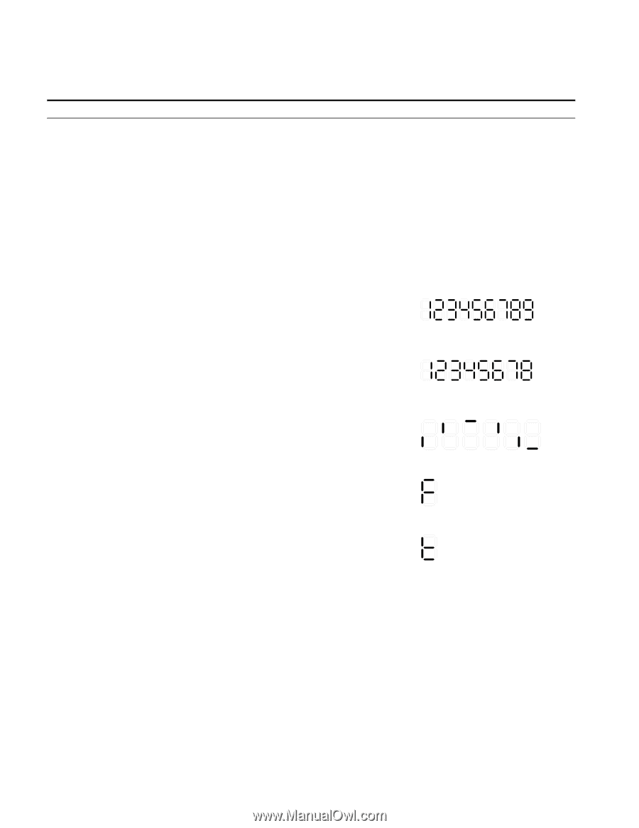
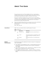
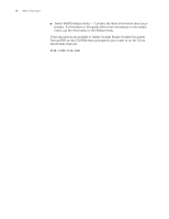
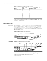
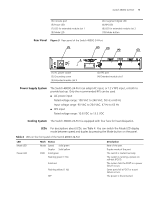
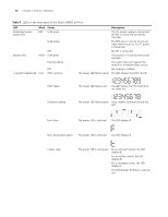
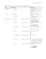
10 CHAPTER 1: PRODUCT OVERVIEW Table 4 LEDs on the front panel of the Switch 4800G 24-Port LED Redundant power system LED Mark Status RPS Solid green Solid yellow Module LED OFF MOD Solid green Flashing yellow OFF 7-segment digital LED Unit POST running Description The AC power supply is normal and the RPS is connected and works normally. The RPS input is normal, but an AC input failure occurs or no AC power is connected. No RPS is connected. The module is in position and works normally. The switch does not support the module or a module failure occurs. No module is installed. The power LED flashes green The LED displays the POST test ID. POST failed The power LED flashes red The LED flashes the POST test ID of the failed test. Software loading The power LED flashes green. A bar rotates clockwise around the LED. Fan failure The power LED is solid red. The LED displays F. Over-temperature alarm The power LED is solid red. The LED displays t. Cluster state The power LED is solid green. For a command switch, the LED displays C. For a member switch, the LED displays S. For a candidate switch, the LED displays c. The LED displays 1 if there is only one unit.
-
 1
1 -
2
-
3
-
4
-
 5
5 -
 6
6 -
 7
7 -
 8
8 -
 9
9 -
 10
10 -
 11
11 -
 12
12 -
 13
13 -
 14
14 -
 15
15 -
16
-
17
-
18
-
19
-
20
-
21
-
22
-
23
-
24
-
25
-
26
-
27
-
28
-
29
-
30
-
31
-
32
-
33
-
34
-
35
-
36
-
37
-
38
-
39
-
40
-
41
-
42
-
43
-
44
-
45
-
46
-
47
-
48
-
49
-
50
-
51
-
52
-
53
-
54
-
55
-
56
-
57
-
58
-
59
-
60
-
61
-
62
-
63
-
64
-
65
-
66
-
67
-
68
-
69
-
70
-
71
-
72
-
73
-
74
-
75
-
76
-
77
-
78
-
79
-
80
-
81
-
82
 |
 |