3Com 4800G Getting Started Guide - Page 9
Rear Panel, Power Supply System, Cooling System, LEDs, Input voltage range: 90 VAC to 264 VAC - switch 24 port
 |
UPC - 662705534183
View all 3Com 4800G manuals
Add to My Manuals
Save this manual to your list of manuals |
Page 9 highlights
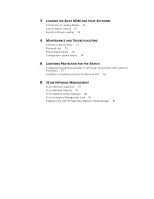
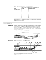
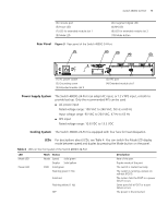
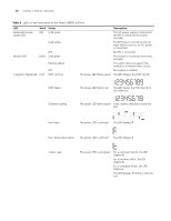
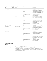
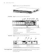
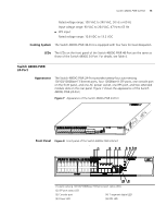
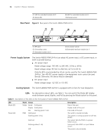
Switch 4800G 24-Port 9 (3) Console port (5) Power LED (7) LED for extended module slot 1 (9) Mode LED (4) 7-segment digital LED (6) RPS LED (8) LED for extended module slot 2 (10) Mode button Rear Panel Figure 3 Rear panel of the Switch 4800G 24-Port (1) (2) (3) (4) (5) (1) AC power socket (3) Grounding screw (5) Extended module slot 2 (2) RPS port (4) Extended module slot 1 Power Supply System The Switch 4800G 24-Port can adopt AC input, or 12 V RPS input, or both to provide backup. Only the recommended RPS can be used. ■ AC power input Rated voltage range: 100 VAC to 240 VAC, 50 Hz or 60 Hz Input voltage range: 90 VAC to 264 VAC, 47 Hz to 63 Hz ■ RPS input Rated voltage range: 10.8 VDC to 13.2 VDC Cooling System The Switch 4800G 24-Port is equipped with four fans for heat dissipation. LEDs For descriptions about LEDs, see Table 4. You can switch the Mode LED display mode between speed and duplex by pressing the Mode button on the panel. Table 4 LEDs on the front panel of the Switch 4800G 24-Port LED Mode LED Power LED Mark Status Mode Speed Solid green Duplex Solid yellow PWR Solid green Flashing green (1 Hz) Solid red Flashing yellow (1 Hz) OFF Description Rate of the port Duplex mode of the port The switch is started normally. The system is running a power-on self-test (POST). The system fails the POST or a power failure occurs. Some ports fail a POST or a port failure occurs. The power is disconnected.
-
 1
1 -
2
-
3
-
 4
4 -
 5
5 -
 6
6 -
 7
7 -
 8
8 -
 9
9 -
 10
10 -
 11
11 -
 12
12 -
 13
13 -
 14
14 -
15
-
16
-
17
-
18
-
19
-
20
-
21
-
22
-
23
-
24
-
25
-
26
-
27
-
28
-
29
-
30
-
31
-
32
-
33
-
34
-
35
-
36
-
37
-
38
-
39
-
40
-
41
-
42
-
43
-
44
-
45
-
46
-
47
-
48
-
49
-
50
-
51
-
52
-
53
-
54
-
55
-
56
-
57
-
58
-
59
-
60
-
61
-
62
-
63
-
64
-
65
-
66
-
67
-
68
-
69
-
70
-
71
-
72
-
73
-
74
-
75
-
76
-
77
-
78
-
79
-
80
-
81
-
82
 |
 |