3Com 4800G Getting Started Guide - Page 49
Removal procedure
 |
UPC - 662705534183
View all 3Com 4800G manuals
Add to My Manuals
Save this manual to your list of manuals |
Page 49 highlights
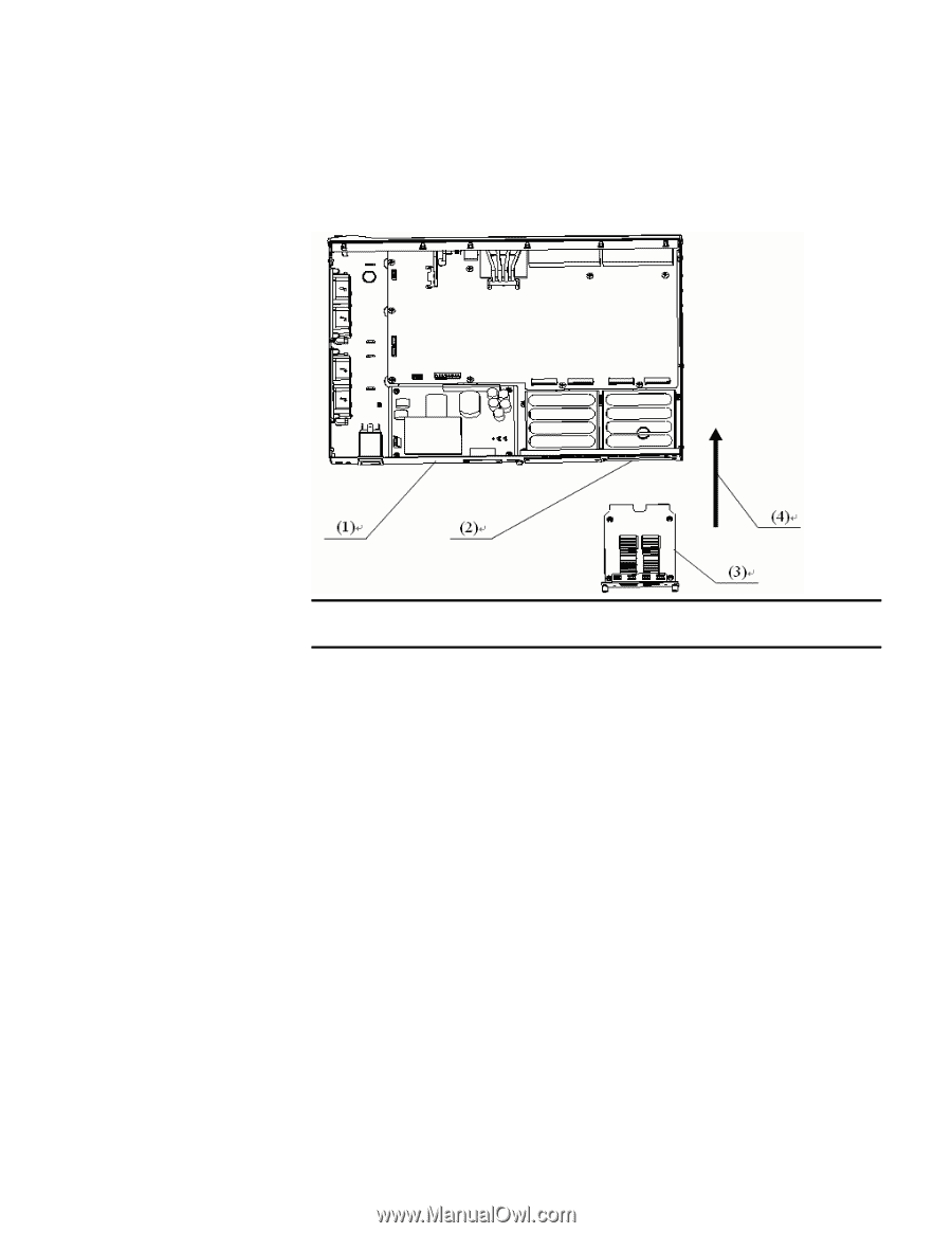
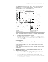
Installing and Removing Optional Interface Modules 49 3 Hold the fastening screws on the front panel of the XFP interface module, and gently push the XFP interface module in along the guide rails until the XFP interface module is in close contact with the switch. Figure 51 Install a 10 GE XFP interface module (1) Switch (3) XFP interface module (2) Optional module slot (4) Push-in direction 4 Tighten the fastening screws with a screwdriver to fix the XFP interface module. n ■ Put away the removed blank panel for future use. ■ When tightening the fastening screws at both sides of an optional interface module with a screwdriver or an electric screwdriver, make sure that the torque is not bigger than 0.4 N.m. Removal procedure 1 Put on an ESD-preventive wrist strap and verify the ESD-preventive wrist strap is properly grounded. 2 Loosen the fastening screws at both sides of the XFP interface module using a Phillips screwdriver. 3 Pull the XFP interface module towards you, until it completely comes out of the switch chassis. c CAUTION: When installing or removing an optional interface module, pay attention to the following points ■ Do not exert a great force on the interface module, and do not touch the surface-mounted components directly with your hands. ■ After removing an optional interface module, if no new module is to be installed, install the blank panel as soon as possible to prevent dust and ensure the normal ventilation in the switch.
-
 1
1 -
2
-
3
-
4
-
5
-
6
-
7
-
8
-
9
-
10
-
11
-
12
-
13
-
14
-
15
-
16
-
17
-
18
-
19
-
20
-
21
-
22
-
23
-
24
-
25
-
26
-
27
-
28
-
29
-
30
-
31
-
32
-
33
-
34
-
35
-
36
-
37
-
38
-
39
-
40
-
41
-
42
-
43
-
 44
44 -
 45
45 -
 46
46 -
 47
47 -
 48
48 -
 49
49 -
 50
50 -
 51
51 -
 52
52 -
 53
53 -
 54
54 -
55
-
56
-
57
-
58
-
59
-
60
-
61
-
62
-
63
-
64
-
65
-
66
-
67
-
68
-
69
-
70
-
71
-
72
-
73
-
74
-
75
-
76
-
77
-
78
-
79
-
80
-
81
-
82
 |
 |