3Com 4800G Getting Started Guide - Page 34
mounting ears is tightly contacted with the load-bearing screw, as shown - weight
 |
UPC - 662705534183
View all 3Com 4800G manuals
Add to My Manuals
Save this manual to your list of manuals |
Page 34 highlights
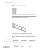
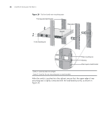
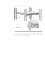
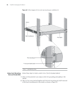
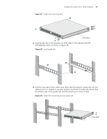
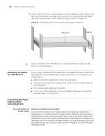
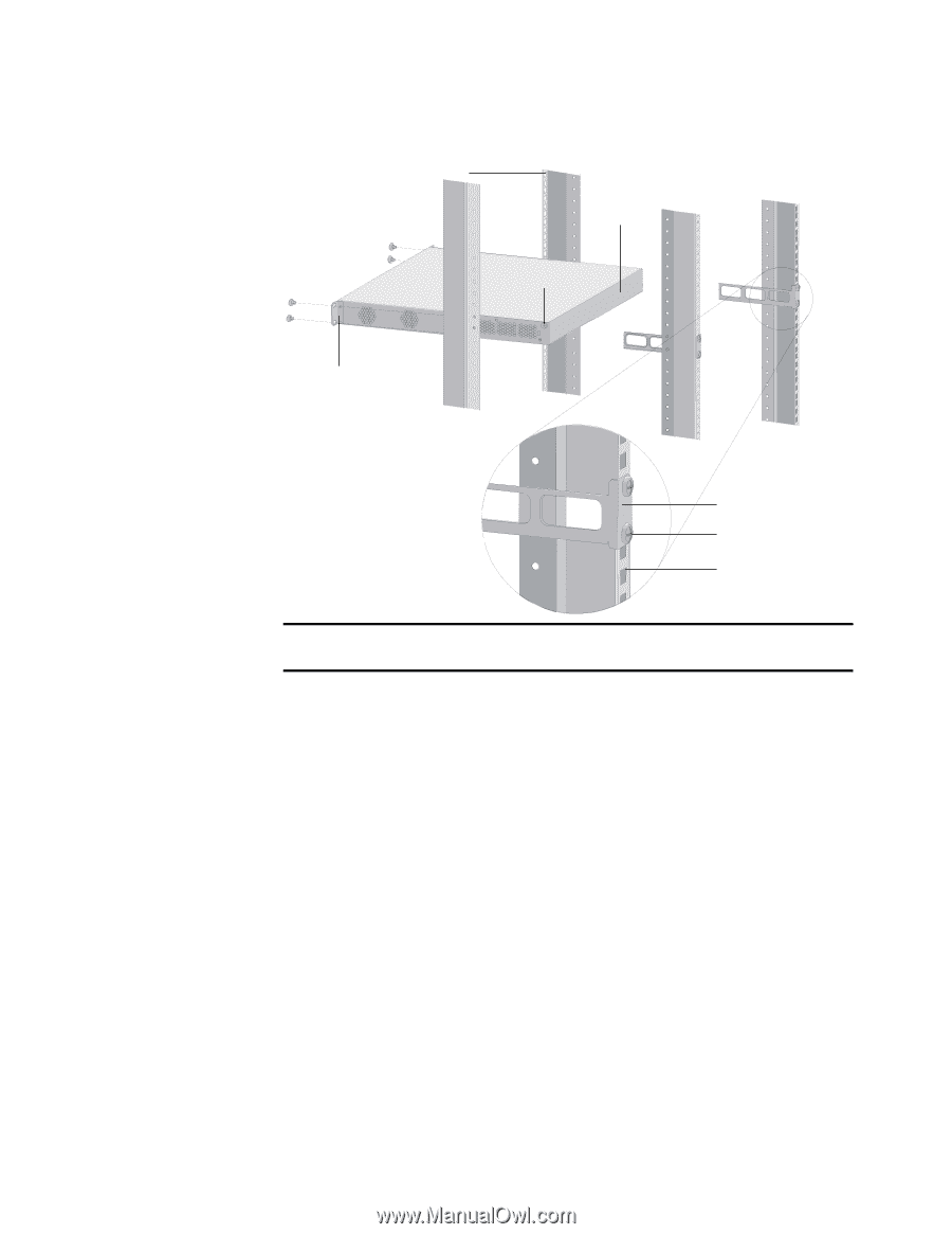
34 CHAPTER 3: INSTALLING THE SWITCH Figure 24 Fix front and rear mounting ears Front square-holed bracket Rear panel Screw 1 Front mounting ear Rear mounting ear Screw 2 Rear square-holed bracket Screw 1: Used to bear the weight Screw 2: Used to fix rear mounting ears to rear brackets After the switch is pushed into the cabinet, ensure that the upper edge of rear mounting ears is tightly contacted with the load-bearing screw, as shown in Figure 25.
-
 1
1 -
2
-
3
-
4
-
5
-
6
-
7
-
8
-
9
-
10
-
11
-
12
-
13
-
14
-
15
-
16
-
17
-
18
-
19
-
20
-
21
-
22
-
23
-
24
-
25
-
26
-
27
-
28
-
 29
29 -
 30
30 -
 31
31 -
 32
32 -
 33
33 -
 34
34 -
 35
35 -
 36
36 -
 37
37 -
 38
38 -
 39
39 -
40
-
41
-
42
-
43
-
44
-
45
-
46
-
47
-
48
-
49
-
50
-
51
-
52
-
53
-
54
-
55
-
56
-
57
-
58
-
59
-
60
-
61
-
62
-
63
-
64
-
65
-
66
-
67
-
68
-
69
-
70
-
71
-
72
-
73
-
74
-
75
-
76
-
77
-
78
-
79
-
80
-
81
-
82
 |
 |
34
C
HAPTER
3: I
NSTALLING
THE
S
WITCH
Figure 24
Fix front and rear mounting ears
After the switch is pushed into the cabinet, ensure that the upper edge of rear
mounting ears is tightly contacted with the load-bearing screw, as shown in
Figure 25.
Screw 1: Used to bear the weight
Screw 2: Used to fix rear mounting ears to rear brackets
Screw 1
Screw 2
Rear mounting ear
Front mounting ear
Front square-holed bracket
Rear panel
Rear square-holed bracket