3Com 4800G Getting Started Guide - Page 44
Connecting the Grounding Cable
 |
UPC - 662705534183
View all 3Com 4800G manuals
Add to My Manuals
Save this manual to your list of manuals |
Page 44 highlights
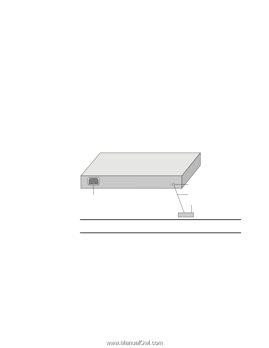
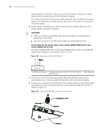
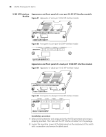
44 CHAPTER 3: INSTALLING THE SWITCH Connecting the Grounding Cable c CAUTION: Correctly connecting the grounding cable is crucial to lightning protection and electromagnetic susceptibility (EMS). The power input end of the switch is equipped with a noise filter, whose central ground is directly connected to the chassis, forming the chassis ground (also known as PGND). This chassis ground must be securely connected to the earth ground so that the faradism and leakage electricity can be safely discharged to the ground, enhancing the EMS capability of the switch. Ground your switch as follows: ■ When a grounding strip is available at the installation site, attach one end of the yellow-green grounding cable of the switch to the grounding terminal on the grounding strip and fasten the captive nut. Note that the fire main and lightning rod of a building are not suitable for grounding. The grounding cable of the switch should be connected to the grounding system in the equipment room. Figure 42 Ground the switch through a grounding strip (2) (3) (1) (4) (1) AC power socket (3) Protection grounding cable (2) Grounding terminal (4) Grounding strip ■ When there is no grounding strip but earth is available near the installation location and allows a grounding body to be buried, hammer an angle iron/steel pipe longer than 0.5 m (1.64 ft) into the earth. Weld the yellow-green grounding cable of the switch onto the angle iron/steel pipe, and treat the joint for corrosion protection.
-
 1
1 -
2
-
3
-
4
-
5
-
6
-
7
-
8
-
9
-
10
-
11
-
12
-
13
-
14
-
15
-
16
-
17
-
18
-
19
-
20
-
21
-
22
-
23
-
24
-
25
-
26
-
27
-
28
-
29
-
30
-
31
-
32
-
33
-
34
-
35
-
36
-
37
-
38
-
 39
39 -
 40
40 -
 41
41 -
 42
42 -
 43
43 -
 44
44 -
 45
45 -
 46
46 -
 47
47 -
 48
48 -
 49
49 -
50
-
51
-
52
-
53
-
54
-
55
-
56
-
57
-
58
-
59
-
60
-
61
-
62
-
63
-
64
-
65
-
66
-
67
-
68
-
69
-
70
-
71
-
72
-
73
-
74
-
75
-
76
-
77
-
78
-
79
-
80
-
81
-
82
 |
 |