3Com 4800G Getting Started Guide - Page 77
Installation precautions, multimeter to confirm that.
 |
UPC - 662705534183
View all 3Com 4800G manuals
Add to My Manuals
Save this manual to your list of manuals |
Page 77 highlights
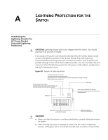
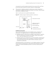
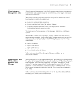
Installing the Lightning Arrester for the Network Port 77 connected to the switch should be inserted into the arrester's OUT end). When you do that, observe whether the arrester indicators normally display. n The instruction of lightning arrester for network port contains the technical specifications, installation and maintenance guide of the arrester. Please carefully read it before installing the arrester. Step 5: Use the nylon ties to bundle the cables neatly. Figure 70 Installation diagram of lightning arrester for network port Network cable indoors Network cable led into from outdoor Power input Switch Lightning arrester for network port (attached onto the chassis) Ground wire of lightning arrester Grounding screw of switch Metal cabinet that contains the switch Installation precautions Fully consider the following items in the installation process, otherwise, the performance of the lightning arrester for network port will be affected: ■ Lightning arrester for network port is installed in reverse direction. In practice, the "IN" end should be connected to the outdoor network cable and the "OUT" end to the network port on the switch. ■ Lightning arrester for the network port is not well grounded. The ground wire for the arrester should be as short as possible, so to ensure its good contact with the grounding screw of the switch. After the connection, use the multimeter to confirm that. The lightning arrester for the network port is not installed completely. If the switch has more than one network ports to interconnect with other devices via cables outdoor, you should install lightning arresters for all these network ports for protection.
-
 1
1 -
2
-
3
-
4
-
5
-
6
-
7
-
8
-
9
-
10
-
11
-
12
-
13
-
14
-
15
-
16
-
17
-
18
-
19
-
20
-
21
-
22
-
23
-
24
-
25
-
26
-
27
-
28
-
29
-
30
-
31
-
32
-
33
-
34
-
35
-
36
-
37
-
38
-
39
-
40
-
41
-
42
-
43
-
44
-
45
-
46
-
47
-
48
-
49
-
50
-
51
-
52
-
53
-
54
-
55
-
56
-
57
-
58
-
59
-
60
-
61
-
62
-
63
-
64
-
65
-
66
-
67
-
68
-
69
-
70
-
71
-
 72
72 -
 73
73 -
 74
74 -
 75
75 -
 76
76 -
 77
77 -
 78
78 -
 79
79 -
 80
80 -
 81
81 -
 82
82
 |
 |