3Com 4800G Getting Started Guide - Page 29
Installing the Switch, Installing the Switch into a 19-Inch Cabinet, Introduction to Mounting Ears, n - open
 |
UPC - 662705534183
View all 3Com 4800G manuals
Add to My Manuals
Save this manual to your list of manuals |
Page 29 highlights
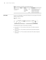
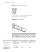
3 INSTALLING THE SWITCH c CAUTION: When you ask your sales agent to maintain the switch, you must ensure that the dismantlement-preventive seal on a mounting screw of the 3Com switch chassis is intact. If you want to open the chassis, you should contact the agent for permission. Otherwise, you will bear any consequence resulting from your actions without permission. Installing the Switch into a 19-Inch Cabinet You can install the switch into a 19-inch standard cabinet in one of the following four ways: ■ Use front mounting ears ■ Use front mounting ears and rear mounting ears ■ Use front mounting ears and a tray ■ Use front mounting ears and guide rails The selection of installation methods depends on the width and depth of the switch. For the installation methods, see Table 12. Table 12 Installation methods for a switch with a width of 440 mm (17.3 in) or 436 mm (17.2 in.) Method/ Depth ≤300 mm (11.8 in) 360 mm (14.2 in.) 420 mm (16.5 in) Use front mounting ears ✔ - - Use front and rear mounting ears ✔ ✔ Use front mounting ears and a tray ✔ ✔ ✔ Use front mounting ears and guide rails ✔ ✔ ✔ n ■ When the depth of a switch is greater than 300 mm (11.8 in), the front mounting ears only secure the switch rather than bear its weight. ■ Guide rails purchased from 3Com apply only to standard cabinets 1,000 mm (39.4 in) deep. Use other supports to substitute for guide rails in the case of other cabinet depths. Introduction to Figure 17 shows the appearance of a front mounting ear. Mounting Ears
-
 1
1 -
2
-
3
-
4
-
5
-
6
-
7
-
8
-
9
-
10
-
11
-
12
-
13
-
14
-
15
-
16
-
17
-
18
-
19
-
20
-
21
-
22
-
23
-
 24
24 -
 25
25 -
 26
26 -
 27
27 -
 28
28 -
 29
29 -
 30
30 -
 31
31 -
 32
32 -
 33
33 -
 34
34 -
35
-
36
-
37
-
38
-
39
-
40
-
41
-
42
-
43
-
44
-
45
-
46
-
47
-
48
-
49
-
50
-
51
-
52
-
53
-
54
-
55
-
56
-
57
-
58
-
59
-
60
-
61
-
62
-
63
-
64
-
65
-
66
-
67
-
68
-
69
-
70
-
71
-
72
-
73
-
74
-
75
-
76
-
77
-
78
-
79
-
80
-
81
-
82
 |
 |