3Com 4800G Getting Started Guide - Page 30
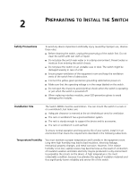
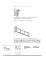
Table 13, shows the appearance of a rear mounting ear.
 |
UPC - 662705534183
View all 3Com 4800G manuals
Add to My Manuals
Save this manual to your list of manuals |
Page 30 highlights
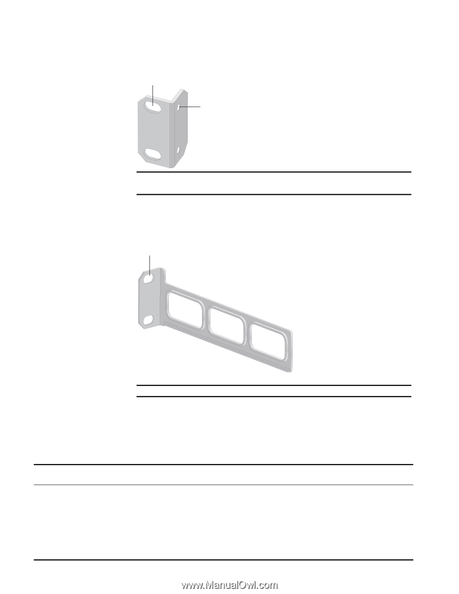
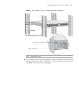
30 CHAPTER 3: INSTALLING THE SWITCH Figure 17 Appearance of a standard front mounting ear (1) (2) (1) Screw hole used to fix the mounting ear to the cabinet (Use one M6 screw) (2) Screw hole used to fix the switch to the mounting ear Figure 18 shows the appearance of a rear mounting ear. Figure 18 Appearance of a rear mounting ear (1) (1) Screw hole used to fix the mounting ear to the cabinet (Use one M6 screw) When you install the switch into a 19-inch standard cabinet, you should select front and rear mounting ears with a proper length (L1 in Figure 17) according to the physical dimensions. For the selection of front and rear mounting ears, see Table 13. Table 13 Selection of mounting ear for the Switch 4800G Model Switch 4800G 24-Port Switch 4800G 24-Port-DC Switch 4800G PWR 48-Port Switch 4800G 48-Port Switch 4800G PWR 24-Port Switch 4800G 24-Port SFP Physical dimensions (H × W × D) 43.6 × 440 × 300 mm (1.72 × 17.3 × 11.8 in.) 43.6 × 440 × 360 mm (1.72 × 17.3 × 14.2 in.) 43.6 × 440 × 420 mm (1.72 × 17.3 × 16.5 in.) Configuration type of front mounting ear Standard Configuration type of rear mounting ear - Standard Standard Standard Standard
-
 1
1 -
2
-
3
-
4
-
5
-
6
-
7
-
8
-
9
-
10
-
11
-
12
-
13
-
14
-
15
-
16
-
17
-
18
-
19
-
20
-
21
-
22
-
23
-
24
-
 25
25 -
 26
26 -
 27
27 -
 28
28 -
 29
29 -
 30
30 -
 31
31 -
 32
32 -
 33
33 -
 34
34 -
 35
35 -
36
-
37
-
38
-
39
-
40
-
41
-
42
-
43
-
44
-
45
-
46
-
47
-
48
-
49
-
50
-
51
-
52
-
53
-
54
-
55
-
56
-
57
-
58
-
59
-
60
-
61
-
62
-
63
-
64
-
65
-
66
-
67
-
68
-
69
-
70
-
71
-
72
-
73
-
74
-
75
-
76
-
77
-
78
-
79
-
80
-
81
-
82
 |
 |