3Com 4800G Getting Started Guide - Page 41
b Connect one connector in the p1 direction of the 12V RPS power cable to
 |
UPC - 662705534183
View all 3Com 4800G manuals
Add to My Manuals
Save this manual to your list of manuals |
Page 41 highlights
Connecting the Power Cables and the Grounding Cable 41 Figure 35 12V RPS power connector Figure 36 12V RPS port a) As shown in Figure 36, loosen the fastening screws and remove the RPS connector cover from the 12V RPS port. (If no 12V RPS power supply is connected, install the cover.) Figure 37 Connect the 12V RPS connector to the chassis b) Connect one connector (in the p1 direction) of the 12V RPS power cable to the RPS port on the switch, making sure that the protruding part is inserted into the
-
 1
1 -
2
-
3
-
4
-
5
-
6
-
7
-
8
-
9
-
10
-
11
-
12
-
13
-
14
-
15
-
16
-
17
-
18
-
19
-
20
-
21
-
22
-
23
-
24
-
25
-
26
-
27
-
28
-
29
-
30
-
31
-
32
-
33
-
34
-
35
-
 36
36 -
 37
37 -
 38
38 -
 39
39 -
 40
40 -
 41
41 -
 42
42 -
 43
43 -
 44
44 -
 45
45 -
 46
46 -
47
-
48
-
49
-
50
-
51
-
52
-
53
-
54
-
55
-
56
-
57
-
58
-
59
-
60
-
61
-
62
-
63
-
64
-
65
-
66
-
67
-
68
-
69
-
70
-
71
-
72
-
73
-
74
-
75
-
76
-
77
-
78
-
79
-
80
-
81
-
82
 |
 |
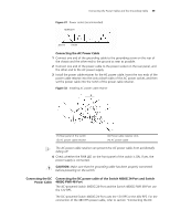
Connecting the Power Cables and the Grounding Cable
41
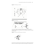
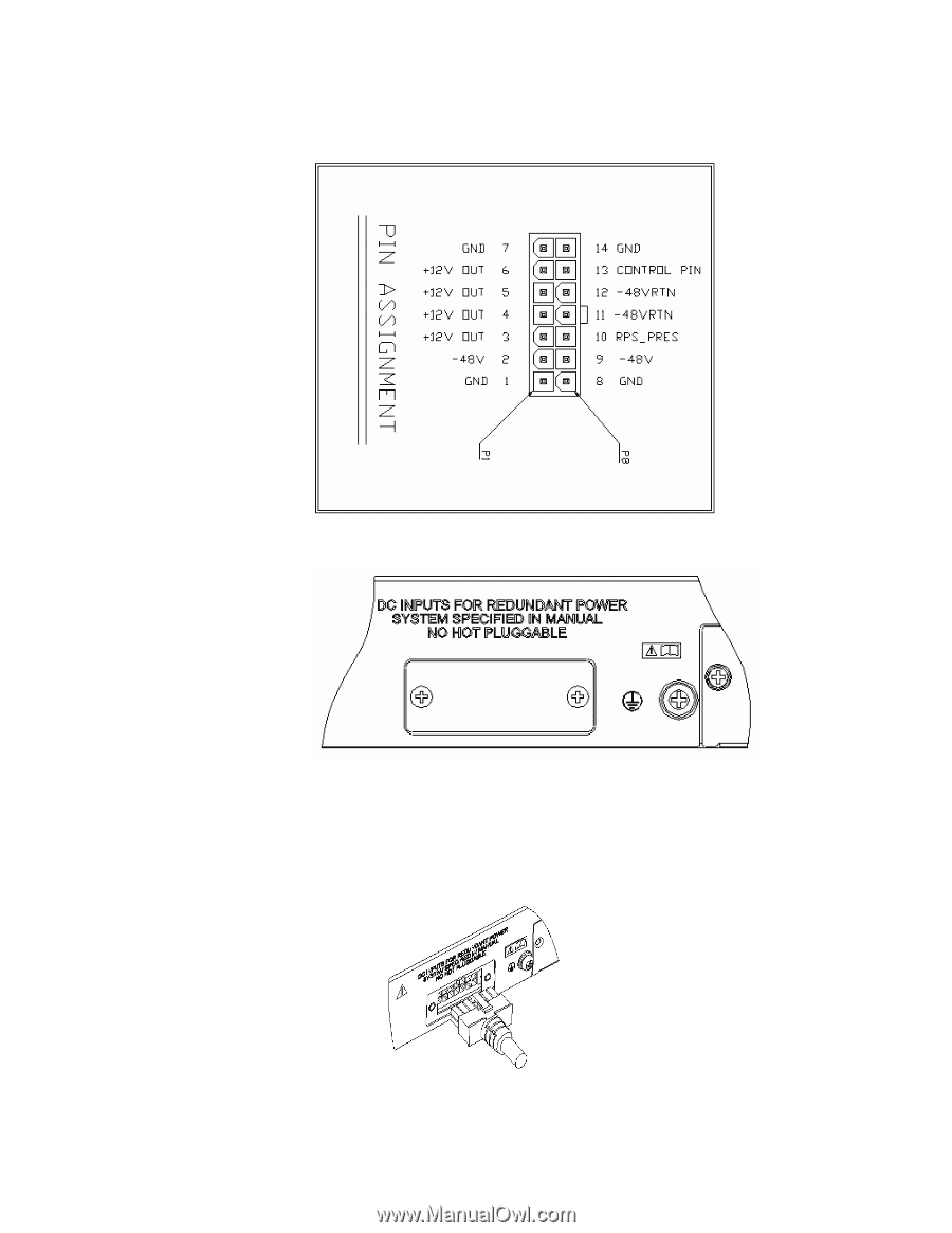
Figure 35
12V RPS power connector
Figure 36
12V RPS port
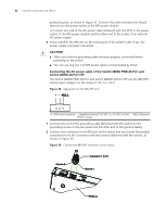
a) As shown in Figure 36, loosen the fastening screws and remove the RPS
connector cover from the 12V RPS port. (If no 12V RPS power supply is connected,
install the cover.)
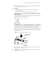
Figure 37
Connect the 12V RPS connector to the chassis
b) Connect one connector (in the p1 direction) of the 12V RPS power cable to the
RPS port on the switch, making sure that the protruding part is inserted into the