3Com 4800G Getting Started Guide - Page 50
Short-haul Dual-port 10 GE CX4 Interface Module, Installing and Removing the Dedicated CX4 Cable
 |
UPC - 662705534183
View all 3Com 4800G manuals
Add to My Manuals
Save this manual to your list of manuals |
Page 50 highlights
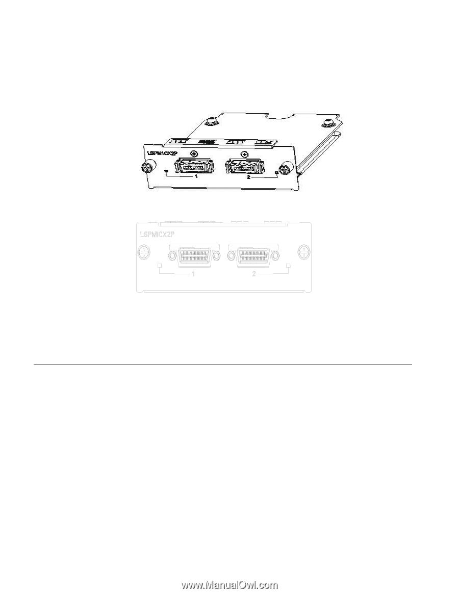
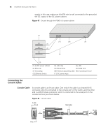
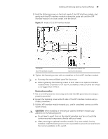
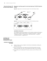
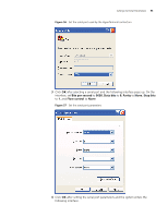
50 CHAPTER 3: INSTALLING THE SWITCH Short-haul Dual-port 10 Appearance and front panel of a short-haul dual-port 10 GE CX4 interface GE CX4 Interface Module module Figure 52 Appearance of a short-haul dual-port 10 GE CX4 interface module Figure 53 Front panel of a short-haul dual-port 10 GE CX4 interface module Installation and removal The installation and removal procedures of CX4 interface modules are the same as those of XFP interface modules. Refer to "Installation procedure" on page 48 "Installation procedure" on page 48 and "Removal procedure" on page 49 "Removal procedure" on page 49 for it. Installing and Removing the Dedicated CX4 Cable Installing the Dedicated CX4 Cable n Make sure that you have installed a CX4 interface module before installing the dedicated CX4 cable. 1 Wear an ESD-preventive wrist strap and verify the ESD-preventive wrist strap properly grounded. Then take out the dedicated CX4 cable from the package. 2 Horizontally insert the dedicated CX4 cable connector into the CX4 port of the switch.
-
 1
1 -
2
-
3
-
4
-
5
-
6
-
7
-
8
-
9
-
10
-
11
-
12
-
13
-
14
-
15
-
16
-
17
-
18
-
19
-
20
-
21
-
22
-
23
-
24
-
25
-
26
-
27
-
28
-
29
-
30
-
31
-
32
-
33
-
34
-
35
-
36
-
37
-
38
-
39
-
40
-
41
-
42
-
43
-
44
-
 45
45 -
 46
46 -
 47
47 -
 48
48 -
 49
49 -
 50
50 -
 51
51 -
 52
52 -
 53
53 -
 54
54 -
 55
55 -
56
-
57
-
58
-
59
-
60
-
61
-
62
-
63
-
64
-
65
-
66
-
67
-
68
-
69
-
70
-
71
-
72
-
73
-
74
-
75
-
76
-
77
-
78
-
79
-
80
-
81
-
82
 |
 |