3Com 4800G Getting Started Guide - Page 40
and the other end to the ground as near as possible.
 |
UPC - 662705534183
View all 3Com 4800G manuals
Add to My Manuals
Save this manual to your list of manuals |
Page 40 highlights
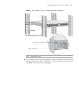
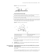
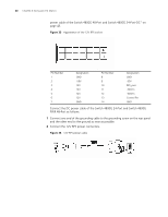
40 CHAPTER 3: INSTALLING THE SWITCH power cable of the Switch 4800G 48-Port and Switch 4800G 24-Port-DC" on page 43. Figure 33 Appearance of the 12V RPS socket Pin Number 1 2 3 4 5 6 7 Designation GND -50V 12V 12V 12V 12V GND Pin Number 8 9 10 11 12 13 14 Designation GND -50V RPS_pres -50Vrtn -50Vrtn Control Pin GND Connect the DC power cable of the Switch 4800G 24-Port and Switch 4800G PWR 48-Port as follows: 1 Connect one end of the grounding cable to the grounding screw on the rear panel and the other end to the ground as near as possible. 2 Connect the 12V RPS power connectors. Figure 34 12V RPS power cable
-
 1
1 -
2
-
3
-
4
-
5
-
6
-
7
-
8
-
9
-
10
-
11
-
12
-
13
-
14
-
15
-
16
-
17
-
18
-
19
-
20
-
21
-
22
-
23
-
24
-
25
-
26
-
27
-
28
-
29
-
30
-
31
-
32
-
33
-
34
-
 35
35 -
 36
36 -
 37
37 -
 38
38 -
 39
39 -
 40
40 -
 41
41 -
 42
42 -
 43
43 -
 44
44 -
 45
45 -
46
-
47
-
48
-
49
-
50
-
51
-
52
-
53
-
54
-
55
-
56
-
57
-
58
-
59
-
60
-
61
-
62
-
63
-
64
-
65
-
66
-
67
-
68
-
69
-
70
-
71
-
72
-
73
-
74
-
75
-
76
-
77
-
78
-
79
-
80
-
81
-
82
 |
 |
40
C
HAPTER
3: I
NSTALLING
THE
S
WITCH
power cable of the Switch 4800G 48-Port and Switch 4800G 24-Port-DC” on
page 43.
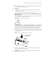
Figure 33
Appearance of the 12V RPS socket
Connect the DC power cable of the Switch 4800G 24-Port and Switch 4800G
PWR 48-Port as follows:
1
Connect one end of the grounding cable to the grounding screw on the rear panel
and the other end to the ground as near as possible.
2
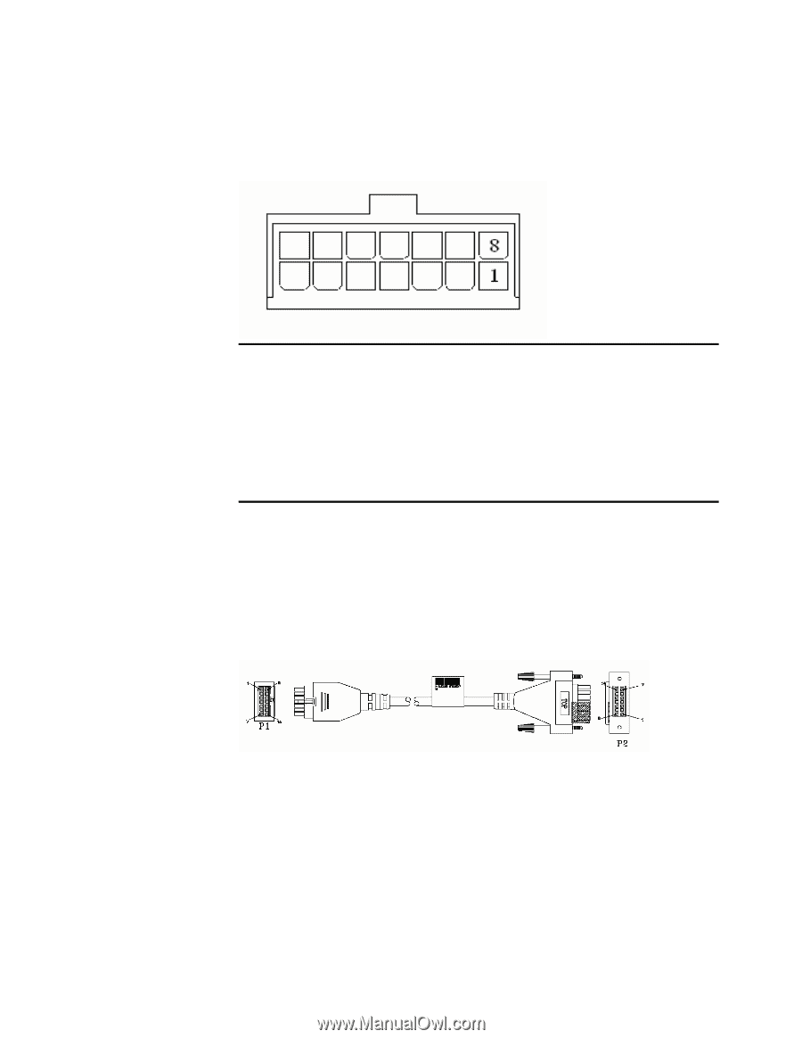
Connect the 12V RPS power connectors.
Figure 34
12V RPS power cable
Pin Number
Designation
Pin Number
Designation
1
GND
8
GND
2
-50V
9
-50V
3
12V
10
RPS_pres
4
12V
11
-50Vrtn
5
12V
12
-50Vrtn
6
12V
13
Control Pin
7
GND
14
GND