3Com 4800G Getting Started Guide - Page 76
Installing the Lightning Arrester for the Network Port, Required tools, Installation procedure
 |
UPC - 662705534183
View all 3Com 4800G manuals
Add to My Manuals
Save this manual to your list of manuals |
Page 76 highlights
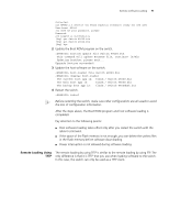
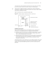
76 CHAPTER A: LIGHTNING PROTECTION FOR THE SWITCH the lightning arrester of power is running and the function of lightning protection has taken effect. ■ Pay adequate attention if the red LED is on. You should correctly locate the problem, whether it is caused because the ground wire of the arrester is not well grounded or because the live and zero wires are connected in reverse direction. You may check that in the following way. When the red LED is on, use a multimeter to examine polarity at the power socket of the arrester. If it is same to that of the power socket in the equipment room, it means that arrester is not well grounded. If it is adverse to that of the power socket in the equipment room, it means that the power socket of the arrester is set to the reverse polarity. In this case, you should open the power socket of arrester to correct polarity. After that, if the red LED still alarms, it means that the arrester is not well grounded yet. Installing the Lightning Arrester for the Network Port n Lightning arrester for network port is specially designed for the Ethernet port of 10/100M electrical interface (RJ-45 connector is adopted in this case). c CAUTION: Lightning arrester for network port will not be provided along with the switch, and you should purchase it by yourself if needed. If an outdoor network cable should be led to the switch, please serially connect the lightning arrester for network port before you plug this cable into the interface on the switch, in case of the possibility that the switch may be damaged due to lightning strike. Required tools ■ Phillips screwdriver or Flat-module screwdriver ■ Multimeter ■ Tilted wire cutter Installation procedure Step 1: Tear the protection paper at one side of the double faced adhesive tape apart from the tape, and stick the tape on the surface of the arrester. Tear the protection paper at another side apart from the tape, and stick the arrester onto the chassis of the switch. The arrester should be attached on the chassis as close to the grounding screw as possible. Step 2: According to the distance to the grounding screw of the switch, cut the ground wire of the arrester, and securely tightening its ground wire to the grounding screw of the switch. Step 3: Use the multimeter to measure whether the ground wire of the arrester contacts well with the grounding screw of chassis. Step 4: According to the instruction of arrester for network port, connect the arrester with switch by the cables (be carefully with the cable direction. Outdoor network cable should be inserted into the arrester's IN end, and the cable
-
 1
1 -
2
-
3
-
4
-
5
-
6
-
7
-
8
-
9
-
10
-
11
-
12
-
13
-
14
-
15
-
16
-
17
-
18
-
19
-
20
-
21
-
22
-
23
-
24
-
25
-
26
-
27
-
28
-
29
-
30
-
31
-
32
-
33
-
34
-
35
-
36
-
37
-
38
-
39
-
40
-
41
-
42
-
43
-
44
-
45
-
46
-
47
-
48
-
49
-
50
-
51
-
52
-
53
-
54
-
55
-
56
-
57
-
58
-
59
-
60
-
61
-
62
-
63
-
64
-
65
-
66
-
67
-
68
-
69
-
70
-
 71
71 -
 72
72 -
 73
73 -
 74
74 -
 75
75 -
 76
76 -
 77
77 -
 78
78 -
 79
79 -
 80
80 -
 81
81 -
82
 |
 |