3Com 4800G Getting Started Guide - Page 39
Connecting the DC Power Cable
 |
UPC - 662705534183
View all 3Com 4800G manuals
Add to My Manuals
Save this manual to your list of manuals |
Page 39 highlights
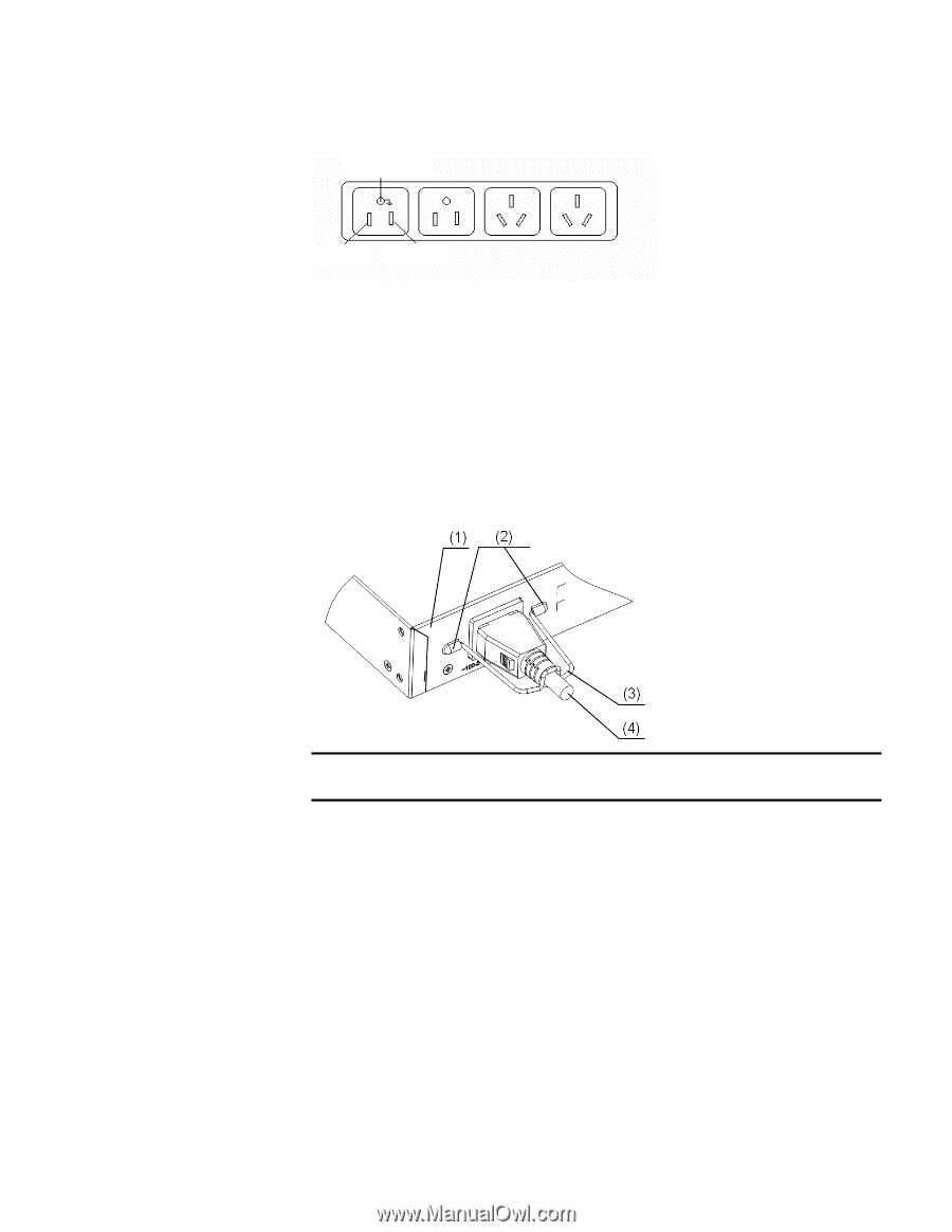
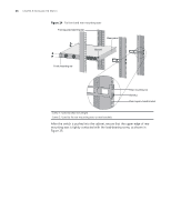
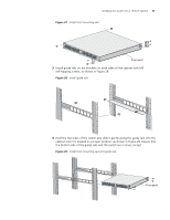
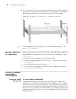
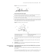
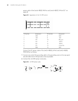
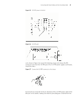
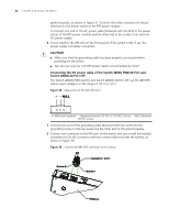
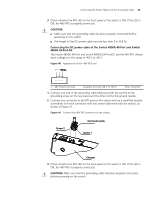
Connecting the Power Cables and the Grounding Cable 39 Figure 31 Power socket (recommended) Neutral point Zero line Live line Connecting the AC Power Cable 1 Connect one end of the grounding cable to the grounding screw on the rear of the chassis and the other end to the ground as near as possible. 2 Connect one end of the power cable to the power socket on the rear panel, and the other end to the AC power supply. 3 Install the power cable retainer for the AC power cable. Insert the two ends of the power cable retainer into the slots at both sides of the AC power socket, and then set the power cable into the notch of the power cable retainer. Figure 32 Installing AC power cable retainer (1) Rear panel of the switch (3) AC power cable retainer (2) Power cable retainer slots (4) AC power cable n The AC power cable retainer can prevent the AC power cable from accidentally falling off. 4 Check whether the PWR LED on the front panel of the switch is ON. If yes, the power supply is connected. c CAUTION: Make sure that the grounding cable has been properly connected before powering on the switch. Connecting the DC Power Cable Connecting the DC power cable of the Switch 4800G 24-Port and Switch 4800G PWR 48-Port The AC-powered Switch 4800G 24-Port and the Switch 4800G PWR 48-Port use the 12V RPS. The DC-powered Switch 4800G 24-Port uses the 12V RPS or the 48V RPS. For the connection of the 48V RPS power cable, refer to section "Connecting the DC
-
 1
1 -
2
-
3
-
4
-
5
-
6
-
7
-
8
-
9
-
10
-
11
-
12
-
13
-
14
-
15
-
16
-
17
-
18
-
19
-
20
-
21
-
22
-
23
-
24
-
25
-
26
-
27
-
28
-
29
-
30
-
31
-
32
-
33
-
 34
34 -
 35
35 -
 36
36 -
 37
37 -
 38
38 -
 39
39 -
 40
40 -
 41
41 -
 42
42 -
 43
43 -
 44
44 -
45
-
46
-
47
-
48
-
49
-
50
-
51
-
52
-
53
-
54
-
55
-
56
-
57
-
58
-
59
-
60
-
61
-
62
-
63
-
64
-
65
-
66
-
67
-
68
-
69
-
70
-
71
-
72
-
73
-
74
-
75
-
76
-
77
-
78
-
79
-
80
-
81
-
82
 |
 |