3Com 4800G Getting Started Guide - Page 31
Introduction to Guide Rails, Using Front Mounting Ears to Install the Switch,
 |
UPC - 662705534183
View all 3Com 4800G manuals
Add to My Manuals
Save this manual to your list of manuals |
Page 31 highlights
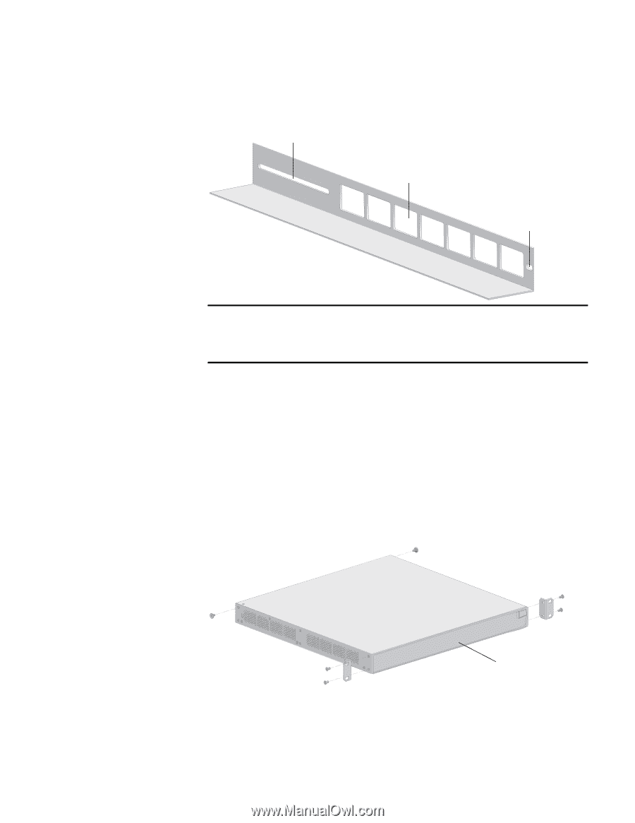
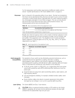
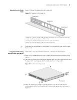
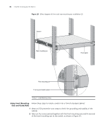
Installing the Switch into a 19-Inch Cabinet 31 Introduction to Guide Figure 19 shows the appearance of a guide rail. Rails Figure 19 Appearance of a guide rail Slotted hole 1 Cooling hole Slotted hole 2 Slotted hole 1: Used to fix the guide rail to the rear bracket. You can adjust the screw hole position according to the position of the switch. Cooling hole: Used for heat dissipation between switch and cabinet Slotted hole 2: Used to fix the guide rail to the front bracket n Guide rails are optional parts. Check Table 12 to see whether you need to order them or not. Using Front Mounting Follow these steps to install the switch into a 19-inch standard cabinet: Ears to Install the Switch 1 Wear an ESD-preventive wrist strap to check the grounding and stability of the cabinet. 2 Take out the screws which are packed together with the front mounting ears, and fix one end of mounting ears to the switch, as shown in Figure 20. Figure 20 Fix front mounting ears (1) Front panel 3 Place the switch horizontally in a proper position, and fix the other end of mounting ears to the front brackets with screws and captive nuts, as shown in Figure 21.
-
 1
1 -
2
-
3
-
4
-
5
-
6
-
7
-
8
-
9
-
10
-
11
-
12
-
13
-
14
-
15
-
16
-
17
-
18
-
19
-
20
-
21
-
22
-
23
-
24
-
25
-
 26
26 -
 27
27 -
 28
28 -
 29
29 -
 30
30 -
 31
31 -
 32
32 -
 33
33 -
 34
34 -
 35
35 -
 36
36 -
37
-
38
-
39
-
40
-
41
-
42
-
43
-
44
-
45
-
46
-
47
-
48
-
49
-
50
-
51
-
52
-
53
-
54
-
55
-
56
-
57
-
58
-
59
-
60
-
61
-
62
-
63
-
64
-
65
-
66
-
67
-
68
-
69
-
70
-
71
-
72
-
73
-
74
-
75
-
76
-
77
-
78
-
79
-
80
-
81
-
82
 |
 |