3Com 4800G Getting Started Guide - Page 33
only two positions on both sides of the Switch 4800G 48-Port. You should select
 |
UPC - 662705534183
View all 3Com 4800G manuals
Add to My Manuals
Save this manual to your list of manuals |
Page 33 highlights
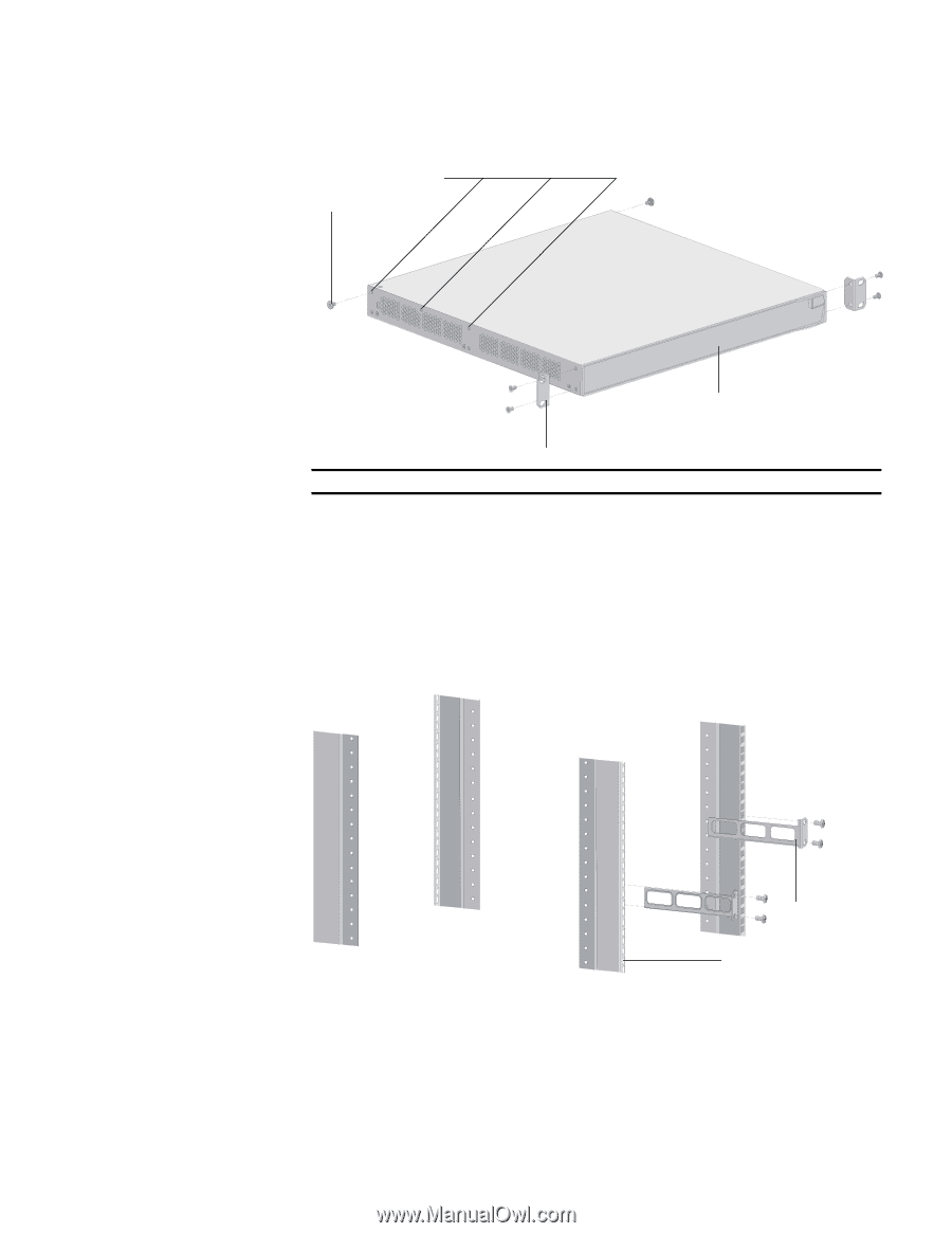
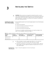
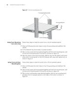
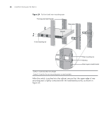
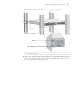
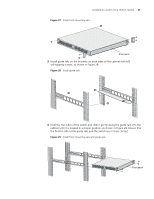
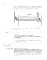
Installing the Switch into a 19-Inch Cabinet 33 Figure 22 Fix front mounting ears and load-bearing screws Screw 1 Optional positions for screw 1 Front panel Front mounting ears Screw 1: Load-bearing screw n There are three positions to mount a load-bearing screw on both sides of a switch (only two positions on both sides of the Switch 4800G 48-Port). You should select a proper position according to the actual requirements. The rear mounting ears support the switch by tightly contacting with the load-bearing screws. 4 Select a position to install the switch and fix the rear mounting ears to the rear brackets with screws and captive nuts, as shown in Figure 23. Figure 23 Fix rear mounting ears Rear mounting ears Rear square-holed bracket 5 Hold the bottom of the switch with one hand and the front part of the switch with the other hand, and push the switch into the cabinet gently, as shown in Figure 24.
-
 1
1 -
2
-
3
-
4
-
5
-
6
-
7
-
8
-
9
-
10
-
11
-
12
-
13
-
14
-
15
-
16
-
17
-
18
-
19
-
20
-
21
-
22
-
23
-
24
-
25
-
26
-
27
-
 28
28 -
 29
29 -
 30
30 -
 31
31 -
 32
32 -
 33
33 -
 34
34 -
 35
35 -
 36
36 -
 37
37 -
 38
38 -
39
-
40
-
41
-
42
-
43
-
44
-
45
-
46
-
47
-
48
-
49
-
50
-
51
-
52
-
53
-
54
-
55
-
56
-
57
-
58
-
59
-
60
-
61
-
62
-
63
-
64
-
65
-
66
-
67
-
68
-
69
-
70
-
71
-
72
-
73
-
74
-
75
-
76
-
77
-
78
-
79
-
80
-
81
-
82
 |
 |