3Com 4800G Getting Started Guide - Page 38
Mounting the Switch on a Workbench, Connecting the Power Cables and the Grounding Cable
 |
UPC - 662705534183
View all 3Com 4800G manuals
Add to My Manuals
Save this manual to your list of manuals |
Page 38 highlights
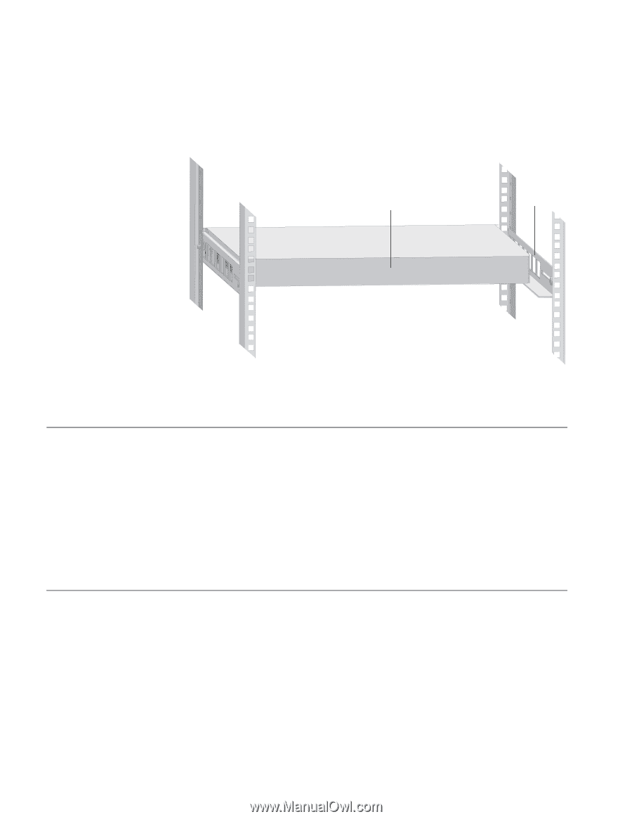
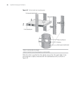
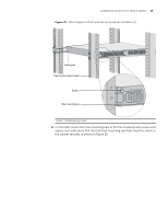
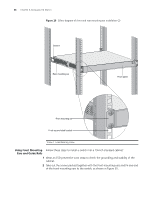
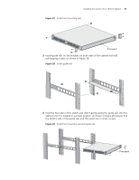
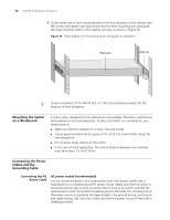
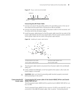
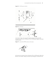
38 CHAPTER 3: INSTALLING THE SWITCH 5 Fix the other end of front mounting ears to the front brackets of the cabinet with M6 screws and captive nuts and ensure that the front mounting ears and guide rails have fixed the switch in the cabinet securely, as shown in Figure 30. Figure 30 Effect diagram of front mounting ear and guide rail installation Rear panel Guide rail n Ensure a clearance of 1U (44.45 mm or 1.75 inches) between devices for the purpose of heat dissipation. Mounting the Switch on a Workbench In many cases, standard 19-inch cabinets are not available. Therefore, switches are often placed on clean workbenches. To place the switch on a workbench, you simply need to: ■ Make sure that the workbench is clean, flat, and sturdy. ■ Ensure good ventilation and a space of 10 cm (3.9 in.) around the chassis for heat dissipation. ■ Do not place heavy objects on the switch. ■ In the case of stack application, the vertical distance between two switches must be at least 1.5 cm (0.59 in). Connecting the Power Cables and the Grounding Cable Connecting the AC Power Cable AC power socket (recommended) You are recommended to use a single-phase three-wire power socket with a neutral point or a multifunctional PC power socket. Make sure that the socket is furnished with an over-current protection device such as air switch and that the neutral point is well connected to building ground. Normally, the neutral point of the power source in a building has been buried in the ground during construction and cable routing. Still, you must make sure that the power source of the build is reliably grounded.
-
 1
1 -
2
-
3
-
4
-
5
-
6
-
7
-
8
-
9
-
10
-
11
-
12
-
13
-
14
-
15
-
16
-
17
-
18
-
19
-
20
-
21
-
22
-
23
-
24
-
25
-
26
-
27
-
28
-
29
-
30
-
31
-
32
-
 33
33 -
 34
34 -
 35
35 -
 36
36 -
 37
37 -
 38
38 -
 39
39 -
 40
40 -
 41
41 -
 42
42 -
 43
43 -
44
-
45
-
46
-
47
-
48
-
49
-
50
-
51
-
52
-
53
-
54
-
55
-
56
-
57
-
58
-
59
-
60
-
61
-
62
-
63
-
64
-
65
-
66
-
67
-
68
-
69
-
70
-
71
-
72
-
73
-
74
-
75
-
76
-
77
-
78
-
79
-
80
-
81
-
82
 |
 |