3Com 4800G Getting Started Guide - Page 43
Connecting the DC power cable of the Switch 4800G 48-Port and Switch, 4800G 24-Port-DC
 |
UPC - 662705534183
View all 3Com 4800G manuals
Add to My Manuals
Save this manual to your list of manuals |
Page 43 highlights
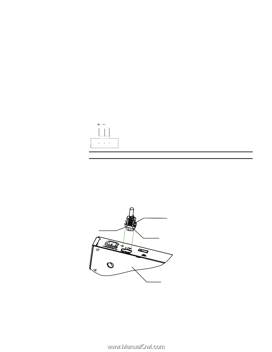
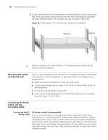
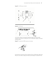
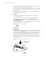
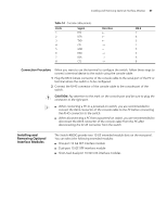
Connecting the Power Cables and the Grounding Cable 43 3 Check whether the RPS LED on the front panel of the switch is ON. If the LED is ON, the 48V RPS is properly connected. c CAUTION: ■ Make sure that the grounding cable has been properly connected before powering on the switch. ■ The length of the DC power cable must be less than 3 m (9.8 ft). Connecting the DC power cable of the Switch 4800G 48-Port and Switch 4800G 24-Port-DC The Switch 4800G 48-Port and Switch 4800G 24-Port-DC use the 48V RPS, whose input voltage is in the range of -48 V to -60 V. Figure 40 Appearance of the -48V RPS port ˇ ˉ NULL +: -48V (return) terminal -: Negative terminal (-48 V to -60 V) NULL: Reserved 1 Connect one end of the grounding cable (delivered with the switch) to the grounding screw on the rear panel and the other end to the ground nearby. 2 Connect one connector to the RPS port on the switch and use a small flat-module screwdriver to fix the connector with two screws (delivered with the switch), as shown in Figure 41. Figure 41 Connect the 48V RPS connector to the chassis Screw 2 Connector parts Screw 1 Chassis 3 Check whether the RPS LED on the front panel of the switch is ON. If the LED is ON, the 48V RPS is properly connected. c CAUTION: Make sure that the grounding cable has been properly connected before powering on the switch.
-
 1
1 -
2
-
3
-
4
-
5
-
6
-
7
-
8
-
9
-
10
-
11
-
12
-
13
-
14
-
15
-
16
-
17
-
18
-
19
-
20
-
21
-
22
-
23
-
24
-
25
-
26
-
27
-
28
-
29
-
30
-
31
-
32
-
33
-
34
-
35
-
36
-
37
-
 38
38 -
 39
39 -
 40
40 -
 41
41 -
 42
42 -
 43
43 -
 44
44 -
 45
45 -
 46
46 -
 47
47 -
 48
48 -
49
-
50
-
51
-
52
-
53
-
54
-
55
-
56
-
57
-
58
-
59
-
60
-
61
-
62
-
63
-
64
-
65
-
66
-
67
-
68
-
69
-
70
-
71
-
72
-
73
-
74
-
75
-
76
-
77
-
78
-
79
-
80
-
81
-
82
 |
 |