3Com 4800G Getting Started Guide - Page 47
Connection Procedure, Installing and Removing Optional Interface Modules
 |
UPC - 662705534183
View all 3Com 4800G manuals
Add to My Manuals
Save this manual to your list of manuals |
Page 47 highlights
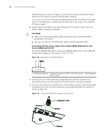
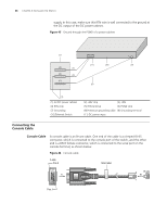
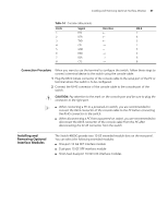
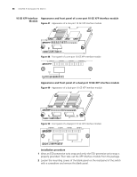
Installing and Removing Optional Interface Modules 47 Table 14 Console cable pinouts RJ-45 1 2 3 4 5 6 7 8 Signal RTS DTR TXD CD GND RXD DSR CTS Direction DB-9 7 4 3 1 5 2 6 8 Connection Procedure When you want to use the terminal to configure the switch, follow these steps to connect a terminal device to the switch using the console cable: 1 Plug the DB-9 female connector of the console cable to the serial port of the PC or terminal where the switch is to be configured. 2 Connect the RJ-45 connector of the console cable to the console port of the switch. c CAUTION: Pay attention to the mark on the console port and be sure to plug the connector to the right port. n ■ When connecting a PC to a powered-on switch, you are recommended to connect the DB-9 connector of the console cable to the PC before connecting the RJ-45 connector to the switch. ■ When disconnecting a PC from a powered-on switch, you are recommended to disconnect the DB-9 connector of the console cable from the PC after disconnecting the RJ-45 connector from the switch. Installing and Removing Optional Interface Modules The Switch 4800G provide two 10 GE extended module slots on the rear panel. You can select the following extended modules: ■ One-port 10 GE XFP interface module ■ Dual-port 10 GE XFP interface module ■ Short-haul dual-port 10 GE CX4 interface modules
-
 1
1 -
2
-
3
-
4
-
5
-
6
-
7
-
8
-
9
-
10
-
11
-
12
-
13
-
14
-
15
-
16
-
17
-
18
-
19
-
20
-
21
-
22
-
23
-
24
-
25
-
26
-
27
-
28
-
29
-
30
-
31
-
32
-
33
-
34
-
35
-
36
-
37
-
38
-
39
-
40
-
41
-
 42
42 -
 43
43 -
 44
44 -
 45
45 -
 46
46 -
 47
47 -
 48
48 -
 49
49 -
 50
50 -
 51
51 -
 52
52 -
53
-
54
-
55
-
56
-
57
-
58
-
59
-
60
-
61
-
62
-
63
-
64
-
65
-
66
-
67
-
68
-
69
-
70
-
71
-
72
-
73
-
74
-
75
-
76
-
77
-
78
-
79
-
80
-
81
-
82
 |
 |