3Com 4800G Getting Started Guide - Page 37
cabinet until it is located in a proper position, as shown in Ensure
 |
UPC - 662705534183
View all 3Com 4800G manuals
Add to My Manuals
Save this manual to your list of manuals |
Page 37 highlights
Installing the Switch into a 19-Inch Cabinet 37 Figure 27 Install front mounting ears Front panel 3 Install guide rails on the brackets on both sides of the cabinet with M5 self-tapping screws, as shown in Figure 28. Figure 28 Install guide rails 4 Hold the two sides of the switch and slide it gently along the guide rails into the cabinet until it is located in a proper position, as shown in Figure 29. Ensure that the bottom side of the guide rails and the switch are in close contact. Figure 29 Install front mounting ears and guide rails Front panel
-
 1
1 -
2
-
3
-
4
-
5
-
6
-
7
-
8
-
9
-
10
-
11
-
12
-
13
-
14
-
15
-
16
-
17
-
18
-
19
-
20
-
21
-
22
-
23
-
24
-
25
-
26
-
27
-
28
-
29
-
30
-
31
-
 32
32 -
 33
33 -
 34
34 -
 35
35 -
 36
36 -
 37
37 -
 38
38 -
 39
39 -
 40
40 -
 41
41 -
 42
42 -
43
-
44
-
45
-
46
-
47
-
48
-
49
-
50
-
51
-
52
-
53
-
54
-
55
-
56
-
57
-
58
-
59
-
60
-
61
-
62
-
63
-
64
-
65
-
66
-
67
-
68
-
69
-
70
-
71
-
72
-
73
-
74
-
75
-
76
-
77
-
78
-
79
-
80
-
81
-
82
 |
 |
Installing the Switch into a 19-Inch Cabinet
37
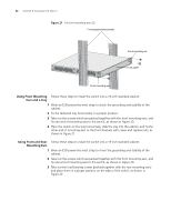
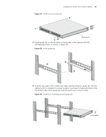
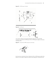
Figure 27
Install front mounting ears
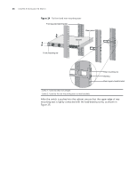
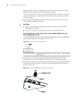
3
Install guide rails on the brackets on both sides of the cabinet with M5
self-tapping screws, as shown in Figure 28.
Figure 28
Install guide rails
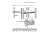
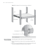
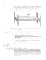
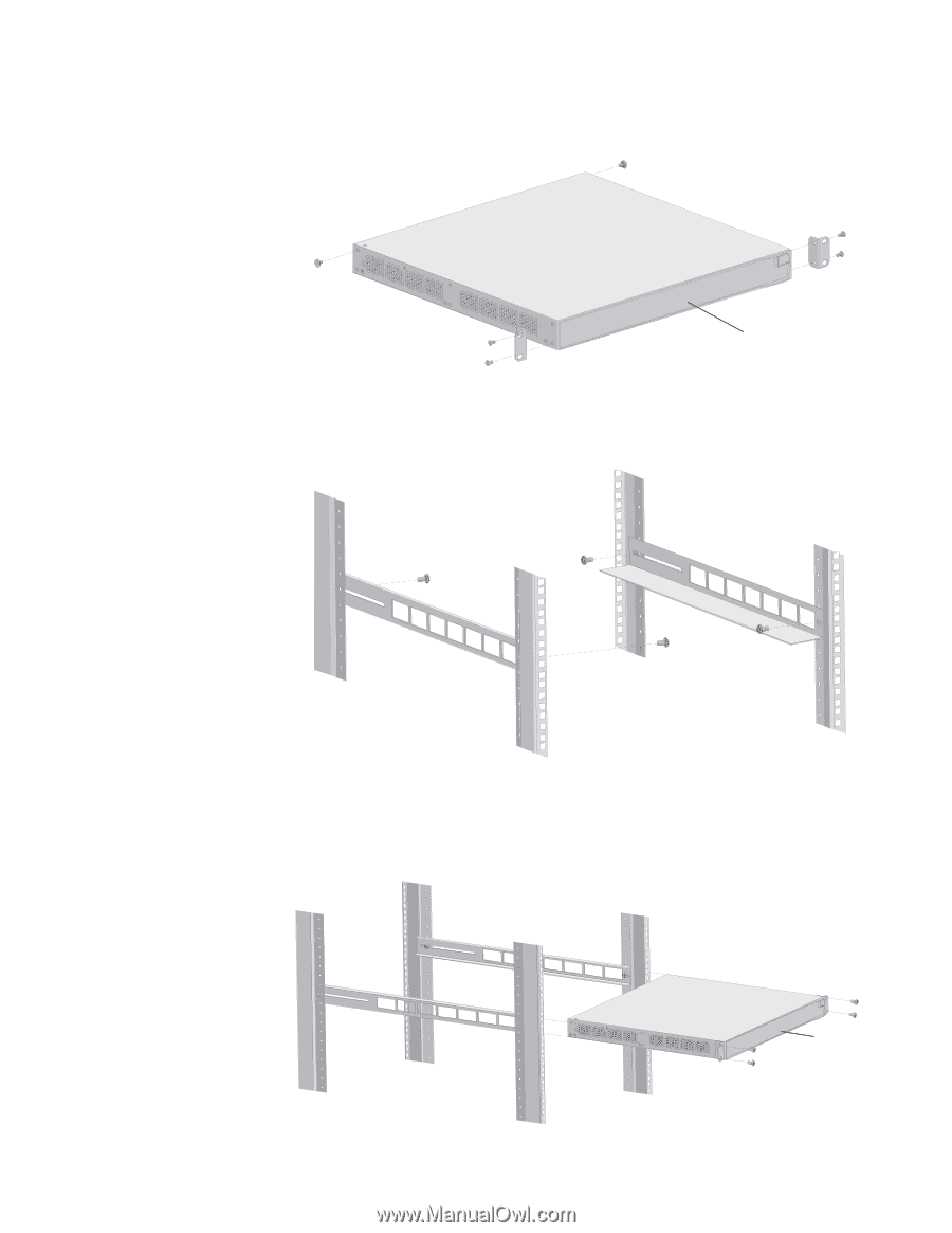
4
Hold the two sides of the switch and slide it gently along the guide rails into the
cabinet until it is located in a proper position, as shown in Figure 29. Ensure that
the bottom side of the guide rails and the switch are in close contact.
Figure 29
Install front mounting ears and guide rails
Front panel
Front panel