Cisco NME-16ES-1G User Guide - Page 3
Switching Frames Between Segments, Building the Address Table, VLAN Trunks - layer 3
 |
UPC - 882658036101
View all Cisco NME-16ES-1G manuals
Add to My Manuals
Save this manual to your list of manuals |
Page 3 highlights
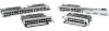
16- and 36-Port Ethernet Switch Module for Cisco 2600 Series, Cisco 3600 Series, and Cisco 3700 Series Feature Overview The Ethernet switch network module solves congestion problems caused by high-bandwidth devices and a large number of users by assigning each device (for example, a server) to its own 10-, 100-, or 1000-Mbps segment. Because each Ethernet interface on the switch represents a separate Ethernet segment, servers in a properly configured switched environment achieve full access to the bandwidth. Because collisions are a major bottleneck in Ethernet networks, an effective solution is full-duplex communication. Normally, Ethernet operates in half-duplex mode, which means that stations can either receive or transmit. In full-duplex mode, two stations can transmit and receive at the same time. When packets can flow in both directions simultaneously, effective Ethernet bandwidth doubles to 20 Mbps for 10-Mbps interfaces and to 200 Mbps for Fast Ethernet interfaces. Switching Frames Between Segments Each Ethernet interface on an Ethernet switch network module can connect to a single workstation or server, or to a hub through which workstations or servers connect to the network. On a typical Ethernet hub, all ports connect to a common backplane within the hub, and the bandwidth of the network is shared by all devices attached to the hub. If two stations establish a session that uses a significant level of bandwidth, the network performance of all other stations attached to the hub is degraded. To reduce degradation, the switch treats each interface as an individual segment. When stations on different interfaces need to communicate, the switch forwards frames from one interface to the other at wire speed to ensure that each session receives full bandwidth. To switch frames between interfaces efficiently, the switch maintains an address table. When a frame enters the switch, it associates the MAC address of the sending station with the interface on which it was received. Building the Address Table The Ethernet switch network module builds the address table by using the source address of the frames received. When the switch receives a frame for a destination address not listed in its address table, it floods the frame to all interfaces of the same virtual local area network (VLAN) except the interface that received the frame. When the destination station replies, the switch adds its relevant source address and interface ID to the address table. The switch then forwards subsequent frames to a single interface without flooding to all interfaces. The address table can store at least 8,191 address entries without flooding any entries. The switch uses an aging mechanism, defined by a configurable aging timer; so if an address remains inactive for a specified number of seconds, it is removed from the address table. Note Default parameters on the aging timer are recommended. VLAN Trunks A trunk is a point-to-point link between one or more Ethernet switch interfaces and another networking device such as a router or a switch. Trunks carry the traffic of multiple VLANs over a single link and allow you to extend VLANs across an entire network and supports only one encapsulation on all Ethernet interfaces: 802.1Q-802.1Q is an industry-standard trunking encapsulation. You can configure a trunk on a single Ethernet interface or on an EtherChannel bundle. For more information about EtherChannel, see the "Configuring Layer 2 EtherChannels (Port-Channel Logical Interfaces)" section on page 56. Cisco IOS Release 12.2(2)XT, 12.2(8)T, and 12.2(15)ZJ 3
-
 1
1 -
 2
2 -
 3
3 -
 4
4 -
 5
5 -
 6
6 -
 7
7 -
 8
8 -
 9
9 -
10
-
11
-
12
-
13
-
14
-
15
-
16
-
17
-
18
-
19
-
20
-
21
-
22
-
23
-
24
-
25
-
26
-
27
-
28
-
29
-
30
-
31
-
32
-
33
-
34
-
35
-
36
-
37
-
38
-
39
-
40
-
41
-
42
-
43
-
44
-
45
-
46
-
47
-
48
-
49
-
50
-
51
-
52
-
53
-
54
-
55
-
56
-
57
-
58
-
59
-
60
-
61
-
62
-
63
-
64
-
65
-
66
-
67
-
68
-
69
-
70
-
71
-
72
-
73
-
74
-
75
-
76
-
77
-
78
-
79
-
80
-
81
-
82
-
83
-
84
-
85
-
86
-
87
-
88
-
89
-
90
-
91
-
92
-
93
-
94
-
95
-
96
-
97
-
98
-
99
-
100
-
101
-
102
-
103
-
104
-
105
-
106
-
107
-
108
-
109
-
110
-
111
-
112
-
113
-
114
-
115
-
116
-
117
-
118
-
119
-
120
-
121
-
122
-
123
-
124
-
125
-
126
-
127
-
128
-
129
-
130
-
131
-
132
-
133
-
134
-
135
-
136
-
137
-
138
-
139
-
140
-
141
-
142
-
143
-
144
-
145
-
146
-
147
-
148
-
149
-
150
-
151
-
152
-
153
-
154
-
155
-
156
-
157
-
158
-
159
-
160
-
161
-
162
-
163
-
164
-
165
-
166
-
167
-
168
-
169
-
170
-
171
-
172
-
173
-
174
-
175
-
176
-
177
-
178
-
179
-
180
-
181
-
182
-
183
-
184
-
185
-
186
-
187
-
188
-
189
-
190
-
191
-
192
-
193
-
194
-
195
-
196
-
197
-
198
-
199
-
200
-
201
-
202
-
203
-
204
-
205
-
206
-
207
-
208
-
209
-
210
-
211
-
212
-
213
-
214
-
215
-
216
-
217
-
218
-
219
-
220
-
221
-
222
-
223
-
224
-
225
-
226
-
227
-
228
-
229
-
230
-
231
-
232
-
233
-
234
-
235
-
236
-
237
-
238
-
239
-
240
-
241
-
242
-
243
-
244
-
245
-
246
 |
 |