Cisco NME-16ES-1G User Guide - Page 42
Fallback Bridging
 |
UPC - 882658036101
View all Cisco NME-16ES-1G manuals
Add to My Manuals
Save this manual to your list of manuals |
Page 42 highlights
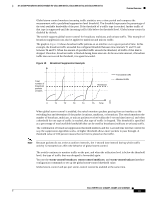
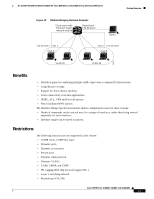
Feature Overview 16- and 36-Port Ethernet Switch Module for Cisco 2600 Series, Cisco 3600 Series, and Cisco 3700 Series Fallback Bridging With fallback bridging, the switch bridges together two or more VLANs or routed ports, essentially connecting multiple VLANs within one bridge domain. Fallback bridging forwards traffic that the multilayer switch does not route and forwards traffic belonging to a nonroutable protocol such as DECnet. Fallback bridging does not allow the spanning trees from the VLANs being bridged to collapse; each VLAN has its own Spanning Tree Protocol (STP) instance and a separate spanning tree, called the VLAN-bridge spanning tree, which runs on top of the bridge group to prevent loops. A VLAN bridge domain is represented using the switch virtual interface (SVI). A set of SVIs and routed ports (which do not have any VLANs associated with them) can be configured to form a bridge group. Recall that an SVI represents a VLAN of switch ports as one interface to the routing or bridging function in the system. Only one SVI can be associated with a VLAN, and it is only necessary to configure an SVI for a VLAN when you want to route between VLANs, to fallback-bridge nonroutable protocols between VLANs, or to provide IP host connectivity to the switch. A routed port is a physical port that acts like a port on a router, but it is not connected to a router. A routed port is not associated with a particular VLAN, does not support subinterfaces, but behaves like a normal routed interface. A bridge group is an internal organization of network interfaces on a switch. Bridge groups cannot be used to identify traffic switched within the bridge group outside the switch on which they are defined. Bridge groups on the same switch function as distinct bridges; that is, bridged traffic and bridge protocol data units (BPDUs) cannot be exchanged between different bridge groups on a switch. An interface can be a member of only one bridge group. Use a bridge group for each separately bridged (topologically distinct) network connected to the switch. The purpose of placing network interfaces into a bridge group is twofold: • To bridge all nonrouted traffic among the network interfaces making up the bridge group. If the packet destination address is in the bridge table, it is forwarded on a single interface in the bridge group. If the packet destination address is not in the bridge table, it is flooded on all forwarding interfaces in the bridge group. The bridge places source addresses in the bridge table as it learns them during the bridging process. • To participate in the spanning-tree algorithm by receiving, and in some cases sending, BPDUs on the LANs to which they are attached. A separate spanning process runs for each configured bridge group. Each bridge group participates in a separate spanning-tree instance. A bridge group establishes a spanning-tree instance based on the BPDUs it receives on only its member interfaces. Figure 19 shows a fallback bridging network example. The multilayer switch has two interfaces configured as SVIs with different assigned IP addresses and attached to two different VLANs. Another interface is configured as a routed port with its own IP address. If all three of these ports are assigned to the same bridge group, non-IP protocol frames can be forwarded among the end stations connected to the switch. Cisco IOS Release 12.2(2)XT, 12.2(8)T, and 12.2(15)ZJ 42
-
 1
1 -
2
-
3
-
4
-
5
-
6
-
7
-
8
-
9
-
10
-
11
-
12
-
13
-
14
-
15
-
16
-
17
-
18
-
19
-
20
-
21
-
22
-
23
-
24
-
25
-
26
-
27
-
28
-
29
-
30
-
31
-
32
-
33
-
34
-
35
-
36
-
 37
37 -
 38
38 -
 39
39 -
 40
40 -
 41
41 -
 42
42 -
 43
43 -
 44
44 -
 45
45 -
 46
46 -
 47
47 -
48
-
49
-
50
-
51
-
52
-
53
-
54
-
55
-
56
-
57
-
58
-
59
-
60
-
61
-
62
-
63
-
64
-
65
-
66
-
67
-
68
-
69
-
70
-
71
-
72
-
73
-
74
-
75
-
76
-
77
-
78
-
79
-
80
-
81
-
82
-
83
-
84
-
85
-
86
-
87
-
88
-
89
-
90
-
91
-
92
-
93
-
94
-
95
-
96
-
97
-
98
-
99
-
100
-
101
-
102
-
103
-
104
-
105
-
106
-
107
-
108
-
109
-
110
-
111
-
112
-
113
-
114
-
115
-
116
-
117
-
118
-
119
-
120
-
121
-
122
-
123
-
124
-
125
-
126
-
127
-
128
-
129
-
130
-
131
-
132
-
133
-
134
-
135
-
136
-
137
-
138
-
139
-
140
-
141
-
142
-
143
-
144
-
145
-
146
-
147
-
148
-
149
-
150
-
151
-
152
-
153
-
154
-
155
-
156
-
157
-
158
-
159
-
160
-
161
-
162
-
163
-
164
-
165
-
166
-
167
-
168
-
169
-
170
-
171
-
172
-
173
-
174
-
175
-
176
-
177
-
178
-
179
-
180
-
181
-
182
-
183
-
184
-
185
-
186
-
187
-
188
-
189
-
190
-
191
-
192
-
193
-
194
-
195
-
196
-
197
-
198
-
199
-
200
-
201
-
202
-
203
-
204
-
205
-
206
-
207
-
208
-
209
-
210
-
211
-
212
-
213
-
214
-
215
-
216
-
217
-
218
-
219
-
220
-
221
-
222
-
223
-
224
-
225
-
226
-
227
-
228
-
229
-
230
-
231
-
232
-
233
-
234
-
235
-
236
-
237
-
238
-
239
-
240
-
241
-
242
-
243
-
244
-
245
-
246
 |
 |